EUKYX-199-2100_G5S2_Instruction_Vol2_E.pdf - 第57页
EUKYX 1-7 199-2100 2.1 Local Window Compo nent H andling Rat e Dat a The data of the feeder where the pick -up rate has been droppe d, is d isp la yed. F2A8 PCB comple tion cy cle Max. 500 items of the measured f in ishi…
EUKYX
1-6199-2100
2.1 Local Window
[4] Data Display Section
The production data, component reload data and component handling rate data parameters are
displayed in this section. Each data display is changed using the button on the lower right of the
display section.
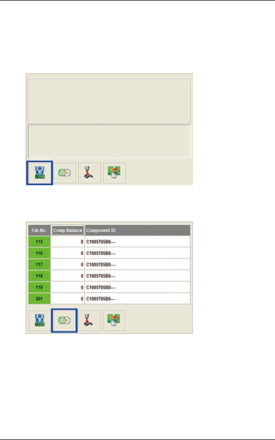
Production Data
When the display change button (left) is pressed, this window appears.
F2A6
Feeder Reload Data
The data of the feeder where the component replenishment is required, is displayed.
F2A7
EUKYX
1-7199-2100
2.1 Local Window
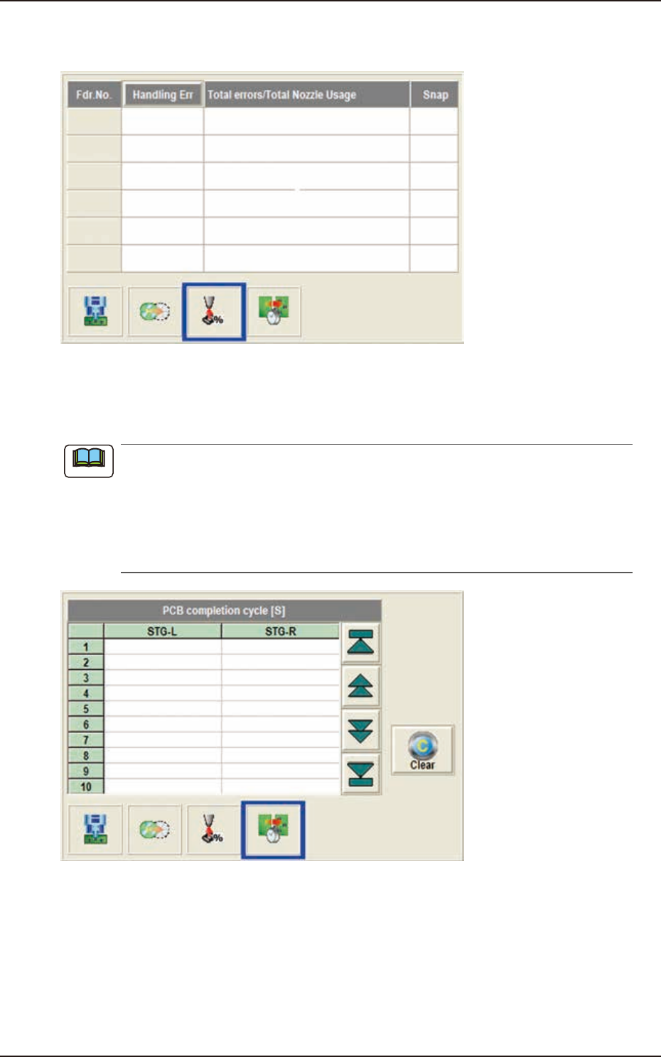
Component Handling Rate Data
The data of the feeder where the pick-up rate has been dropped, is displayed.
F2A8
PCB completion cycle
Max. 500 items of the measured finishing interval (interval between the previous PCB and the
current PCB at the final step completion) are displayed from the newest.
(a) Because the interval cannot be measured before the second PCB is completed, "---" is
displayed at the first PCB finished time.
(b) In the case that the placement status becomes "Stopping" or "Pause", the measurement of
the PCB is stopped and "---" is displayed.
(c) The history is automatically saved in "D:\mdata\MachDt\PcbInt.csy" when the whole
status becomes "Stopping".
F2A9
[5] Stop Mode
[All PCB out] Button
After the PCB in the course of the production, has been produced, the PCB is discharged
and the automatic production operation is stopped.
[Cycle] Button
When the component placement operations on the PCBs in the course of the production in
each of the stage 1 and stage 2, have been completed, the automatic production operation is
stopped.
Note
EUKYX
1-8199-2100
2.2 Line Window
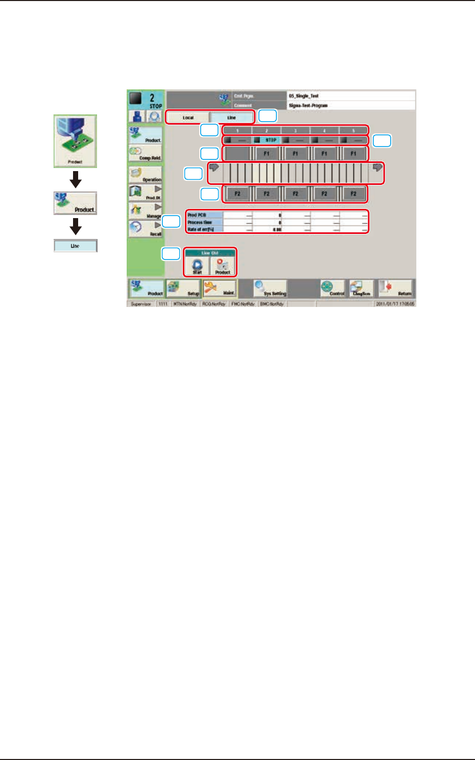
2.2 Line Window
This window enables the operator to check the production line operation status and operate the
line. In this window, the operation status of the SIGMA series machines (including the printer) set in
the line configuration, PCB transfer unit graphic image and production data are displayed.
[1]
[6]
[5]
[7]
[3]
[4]
[5]
[2]
Graphic
Development
F2A10
[1] Local / Line Change Buttons
Using these buttons, the Local window is changed to or from the Line window.
[2] No.
In this area, the machine Nos. in the line are displayed.
[3] Operation Status
In this area, the operation status of each machine in the line, is displayed.
RUN : This machine is under operation.
STOP : This machine is shut down.
PAUSE : This machine is stopped temporarily.
[4] PCB transfer section
In this area, the operation status of each machine in the line, is displayed.
Green : PCB present
Gray : PCB absent
[5] Feeder Base Unit
In this area, the presence or absence of the feeder base is displayed.