EUKYX-199-2100_G5S2_Instruction_Vol2_E.pdf - 第146页
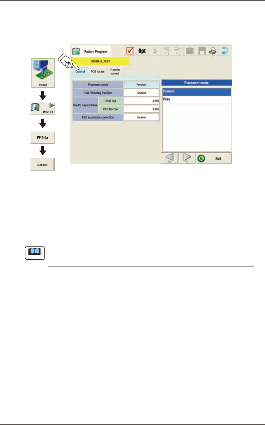
EUKYX 2-33 199-2100 3.4 Control 3.4 Control (D0 1 ) Control D ata When the [ Control] tab is pressed in the "Control" wi ndow , the fol lowi ng tab shee t appears. Graphic Development F2B30 ( D 01_ 01) Placemen…
EUKYX
2-32199-2100
3.3 Operation
(C05_05)
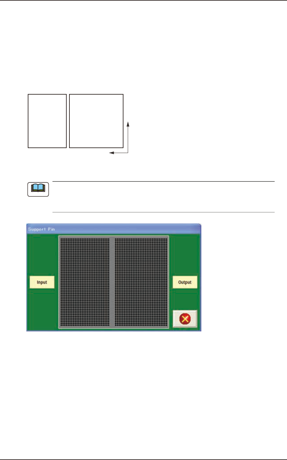
M-X, M-Y
Using these selection boxes, the support pin placement coordinates (M-X, M-Y) are setup.
Coord X, Coord Y
The set support pin coordinates are displayed in these data boxes.
• Data Input Range
Input: M-X : 1 to 30 / M-Y : 1 to 50
Output: M-X : 1 to 30 / M-Y : 1 to 50
Y
X
Input Output
F2B28
When the [Pin] button is pressed, the "Support Pin" dialogue box is opened and the support
pin positions can be checked.
When the [Clear] button is pressed, the support pins with the selected Nos. are cleared.
F2B29
Note
EUKYX
2-33199-2100
3.4 Control
3.4 Control
(D01) Control Data
When the [Control] tab is pressed in the "Control" window, the following tab sheet appears.
Graphic
Development
F2B30
(D01_01)
Placement Mode
"Product" or "Pass" is selected for the placement mode in this pane.
Normally, "Product" is selected.
Product : When selected, the placement operation is performed.
Pass : When selected, the PCB is passed without placement.
When the pattern program set to "Pass" is setup on the Pattern Program Data on “Setup“
- “Prgm Chg.“ window, the vacuum pump is automatically turned OFF.
Note
EUKYX
2-34199-2100
3.4 Control
(D01_02)
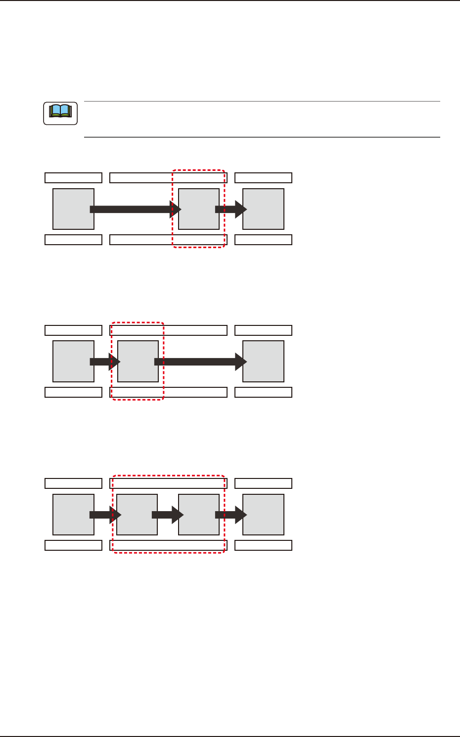
PCB Finishing Position
The PCB Finishing Position is selected in this text box.
Output
The component placement is performed on the downstream side.
For the PCB with the size of 260 mm or more in the X-direction, the components are to be
placed in the downstream side.
Process Position
F2B31
Input
The component placement is performed on the upstream side.
Process Position
F2B32
Sequential
The component placement is performed on the upstream and downstream sides successively.
Process Position
F2B33
Note