EUKYX-199-2100_G5S2_Instruction_Vol2_E.pdf - 第70页
EUKYX 1-20 199-2100 4.1 "Run Mode" T ab Sheet Star ting Proc edure fo r the S emi-A uto St ep Designat ion (1 ) T ransfe r the P CB to the d esignate d tabl e. T ransfer the PCB manual ly to t he ai med positio…
EUKYX
1-19199-2100
4.1 "Run Mode" Tab Sheet
4.1.1 With the start of step described
This function is used when the step is designated in the component reload, recovery or test PCB
placement operation, etc.
There are two types of start with the step designated: Semi-Auto Step and Semi-Auto Step Any
Desig (free designation).
The display window and start procedure are described as follows.
• Description of Semi-Auto Step
A single step operation (1 component/point) can be designated.
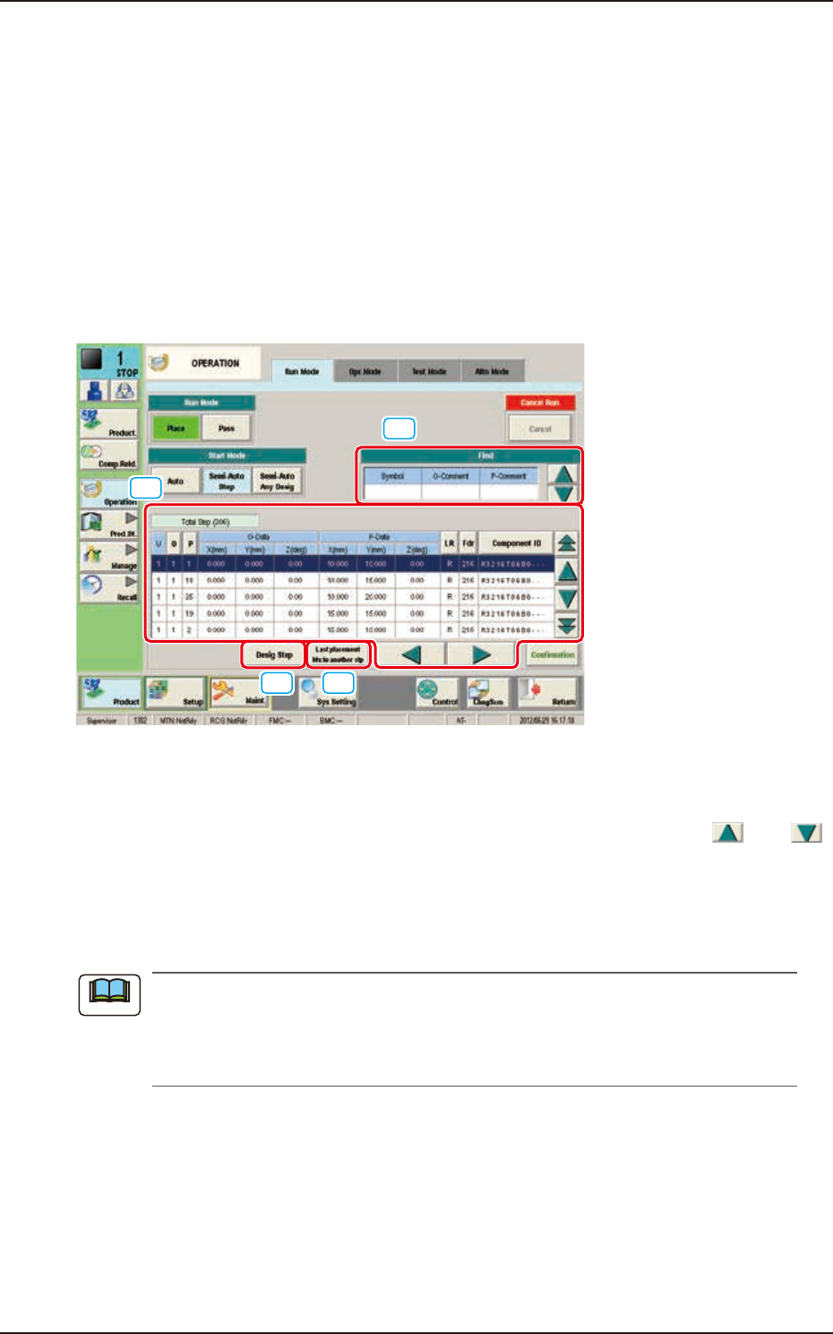
Description of "Semi-Auto Step" Window
When the [Semi-Auto Step] button is pressed in the "Start Mode" group box, the following window
appears.
[1]
[2]
[3] [4]
F2A18
[1] "Find" (Search) Section
The search can be performed with "Symbol", "O Comment" and "P Comment" data. Entering the set
parameters in "Symbol", "O Comment" and "P Comment" data box and pressing the [
] or [
] button designate the entered step.
[2] Step Display Section
The No. of total steps in the pattern program set in the machine, is displayed in this section.
Setting the cursor on the step can also designate the step.
In normal cases, the starting step Nos. are displayed in the order of actual component
placement. By pressing the [O] or the [P] button, the steps can be re-arranged in the ascending
order. Even when the step Nos. are rearranged, the component placement order is not
changed.
[3] [Desig Step] Button
The step No. can be entered and designate in the entry window displayed by pressing the [Desig
Step] button. Enter the step No. in the order of “U”, “O” and “P”.
[4] [Last placement Mv.to another stp] Button
When this button is pressed, the step is moved to the “Last placement Mv. to another stp” (final
placement step) position.
Note
EUKYX
1-20199-2100
4.1 "Run Mode" Tab Sheet
Starting Procedure for the Semi-Auto Step Designation
(1) Transfer the PCB to the designated table.
Transfer the PCB manually to the aimed position.
(2) Designate the step to be started using either of the above procedures.
The background of the designated step is turned in blue.
(3)
When the [START] button on the operation panel is pressed, the designated step mounting is started.
• Description of Semi-Auto Step Any Desig (free designation)
Two or more steps can be designated.
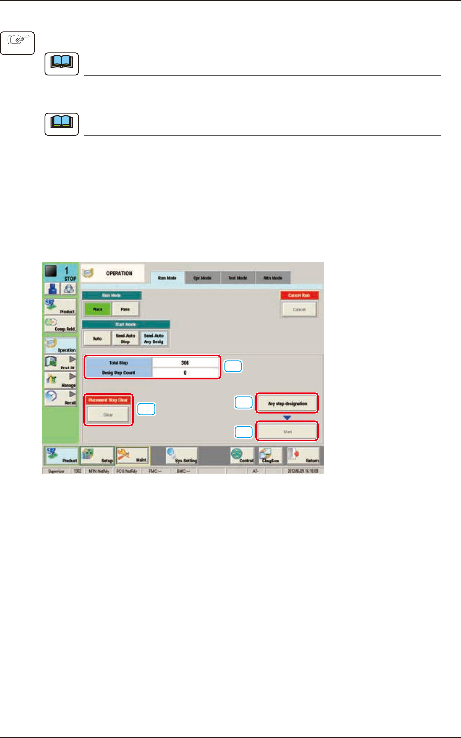
Description of “Semi-Auto Step Any Desig” Window
When the [Semi-Auto Step Any Desig] button is pressed in the “Start Mode” group box, the
following window appears.
[1]
[2]
[3]
[4]
F2A19
[1] No. of Total Steps and Designated Step Count Display Section
The No. of total steps and No. of designated steps are displayed in this section.
[2] [Any step designation] Button
When this button is pressed, the “Any Step Designation” Window appears.
[3] [Start] Button
When this button is pressed, the designated step operation is started.
[4] [Placement Step Clear] Button
When this button is pressed, the placement step operation designated in the “Any Step Designation”
mode, is cleared.
Procedure
Note
Note
EUKYX
1-21199-2100
4.1 "Run Mode" Tab Sheet
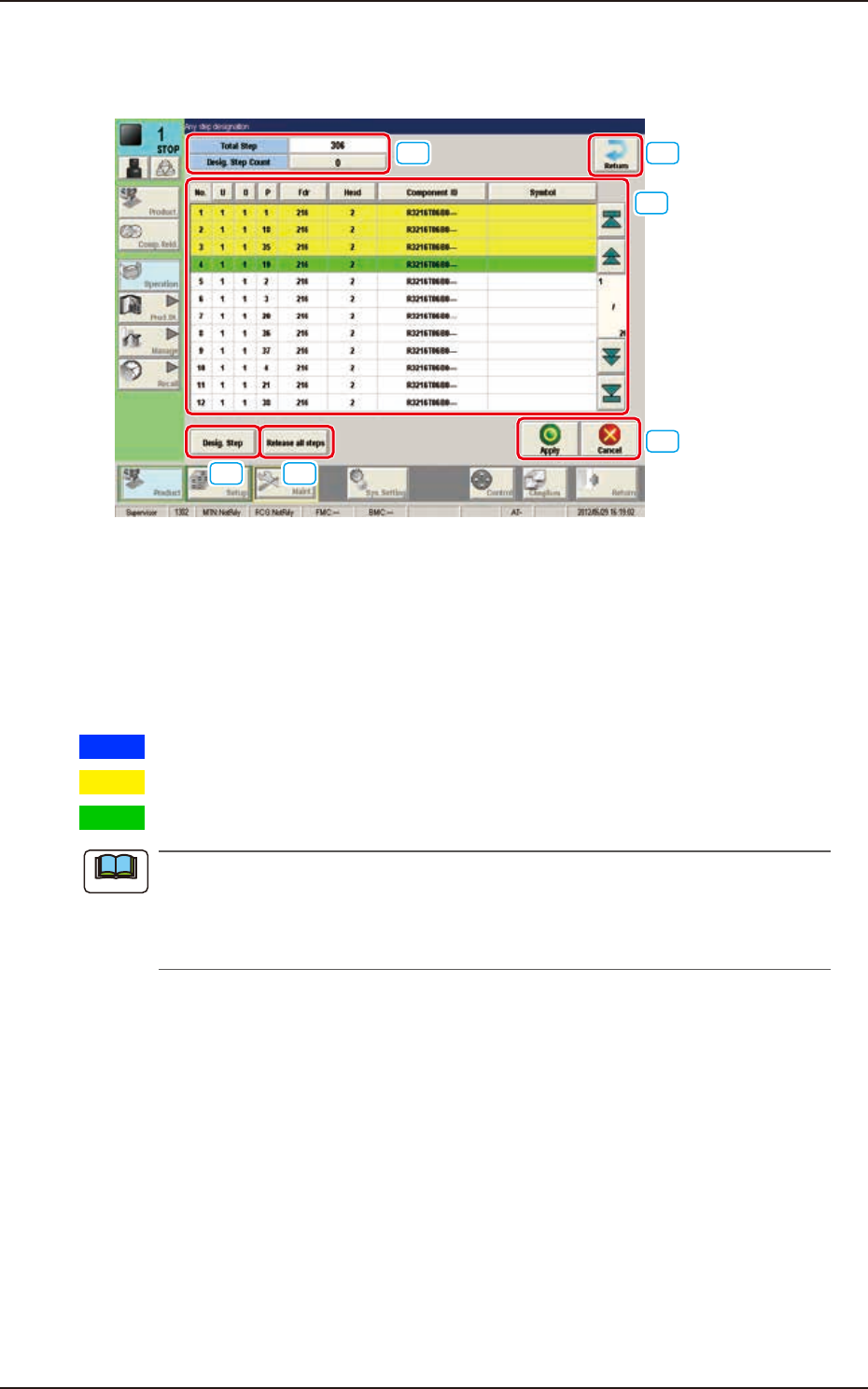
Description of "Any step designation" Window
When the [Any step designation] button is pressed in the "Semi-Auto Step Any Desig" Window, the
following window appears.
[1]
[2]
[3] [4]
[5]
[6]
F2A20
[1] No. of Total Steps and Designated Step Count Display Section
The No. of total steps and No. of designated steps are displayed in this section.
[2] Step Display Section
The total No. of steps in the pattern program set in the machine, is displayed.
Setting the cursor on the step item in the list, designates the step. The background color changes as
follows.
Blue
: This shows the moved step, which has not been designated.
Yellow
: This shows the step, which has already been designated.
Green
: This shows the step, which has been last designated.
In normal cases, the starting step Nos. are displayed in the order of actual component
placement. By pressing the [O] or the [P] button, the steps can be re-arranged in the ascending
order. Even when the step Nos. are rearranged, the component placement order is not
changed.
[3] [Desig.Step] Button
The step No. can be entered and designate in the entry window displayed by pressing the [Desig
Step] button. Enter the step No. in the order of "U", "O" and "P".
[4] [Release all steps] Button
When this button is pressed, all the designated steps and applied steps are cleared.
[5] [Apply] Button
When this button is pressed, the designated step or cleared step is applied.
[Cancel] Button
When this button is pressed, the cleared step is cancelled.
[6] [Return] Button
When this button is pressed, the “Semi-Auto Any Desig” window is returned.
Note