EUKYX-199-2100_G5S2_Instruction_Vol2_E.pdf - 第223页
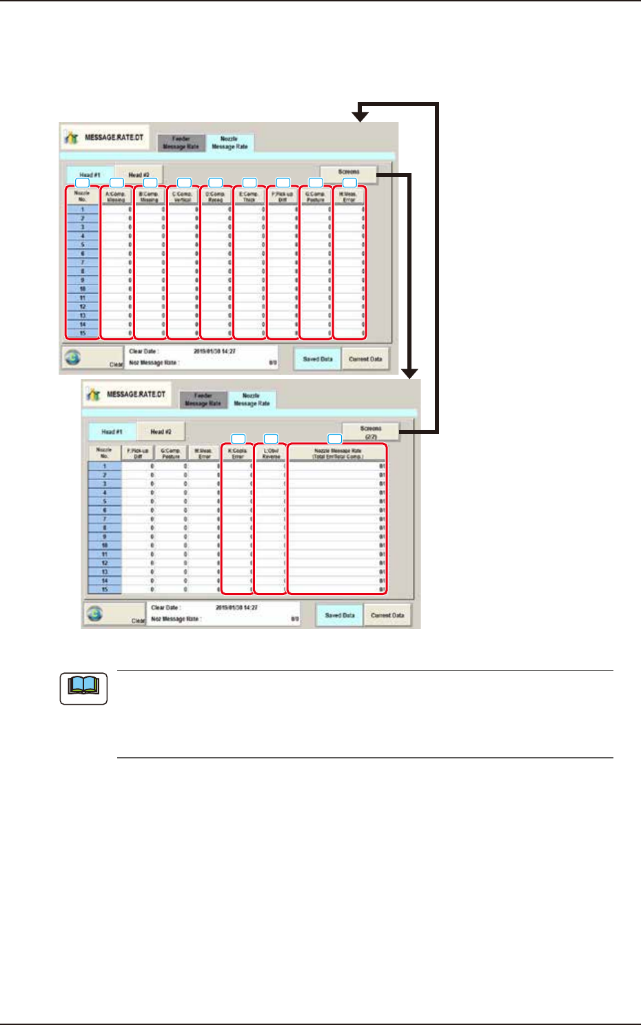
EUKYX 4-31 199-2100 4.2 "Nozzle Message Rate" T ab Sheet [ 1 ] Nozzl e No. Shown are the no z zle N os. [2] A:Comp. Missi ng Each te xt box shows the nu mber of miss ing components detec ted by the li near mea …
EUKYX
4-30199-2100
4.2 "Nozzle Message Rate" Tab Sheet
4.2 "Nozzle Message Rate" Tab Sheet
The corresponding tab sheet enables the operator to view the nozzle management data for each
nozzle/head.
[1]
[2]
[3]
[4] [6]
[7] [8][5]
[9]
[10] [11] [12]
F2D24
(a) The displayed tab sheet will look different, depending on which option is selected.
(b) Pressing one of the buttons displays the data in descending order. This is the order of
error counts, making it easy to analyze and improve production rate. Pressing the [Nozzle
No.] button returns to the default display (Order of Nozzle No.).
The window to display the feeder pickup information per feeder base is divided
Pressing the [Fdr #1] or [Fdr #2] button displays the relevant feeder base window.
Note

EUKYX
4-31199-2100
4.2 "Nozzle Message Rate" Tab Sheet
[1] Nozzle No.
Shown are the nozzle Nos.
[2] A:Comp. Missing
Each text box shows the number of missing components detected by the linear measure detection
sensor for each individual nozzles.
[3] B:Comp. Missing
Each text box shows the number of missing components detected through recognition operation for
each individual nozzles.
[4] C:Comp. Vertical
Each text box shows the number of vertical component errors detected by the linear measure
detection sensor for each individual nozzles.
[5] D:Comp. Recog.
Each text box shows the number of errors detected through recognition operation for each
individual nozzles.
[6] E:Comp. Thick
Each text box shows the number of errors in component thickness detected by the linear measure
detection sensor for each individual nozzles.
[7] F:Pick-up Diff
Each text box shows the number of pickup difference errors detected in the recognition process for
each individual nozzles.
[8] G:Comp. Posture
Each text box shows the number of reversed component and polarity judgment errors detected in
the recognition process for each individual nozzles.
[9] H:Meas. Error
The No. of measurement error total times for each nozzle feeder is displayed in this data box.
[10] K:Copla. Error
The times of error decided in the coplanarity error detection is shown in this data box.
[11] L:Obv/Reverse
The “judged front/rear error” times for each nozzle, detected using the linear measure, is displayed
in these data boxes.
[12] Nozzle Message Rate
(Total Err / Total Comp.)
Each text box shows the rate of pickup errors (the number of pickup errors per number of picked
component) for each nozzle.

199-2100
Chapter 5
Recall
This chapter describes the indication description and operation
procedure for the Device Error, Detection Error and Machine
Information, etc.
1. Outline of “Recall” Window
2. “Device Err” Window
3. “Comp Rcg Err” Window
4. “Comp Err(Sens)” Window
5. “Mach Info” Window
6. “RECOG IMAGE” Window
EUKYX