EUKYX-199-2100_G5S2_Instruction_Vol2_E.pdf - 第144页
EUKYX 2-31 199-2100 3.3 Operation (C05_02) Sup po rt Pin Us ing thi s selection button, it is set whether or not the suppor t pi ns are setup autom ati cal ly in the pat t er n pr og ram change op er ation. (C05_03) The …
EUKYX
2-30199-2100
3.3 Operation
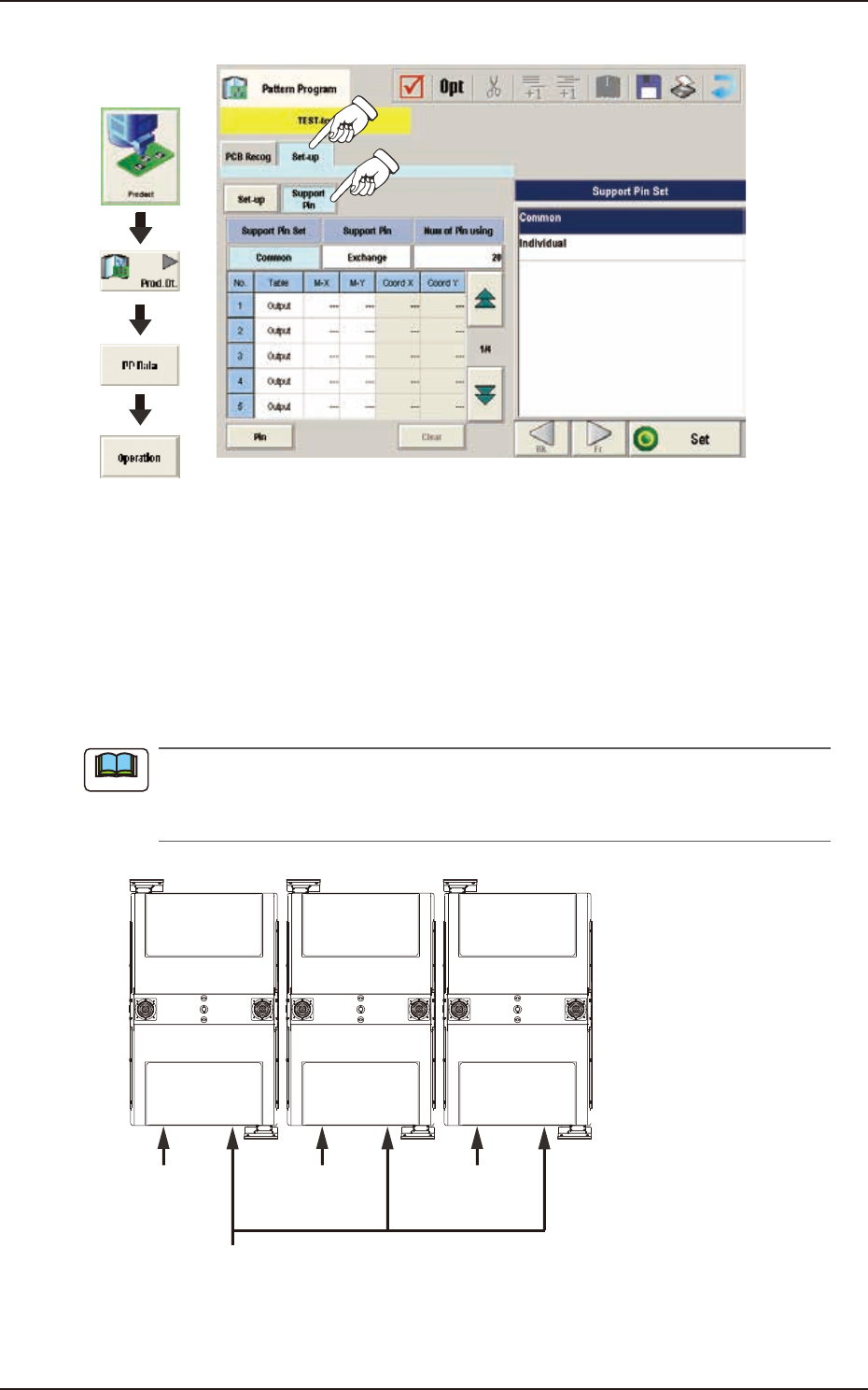
(C05) Support Pin Data
Graphic
Development
F2B25
(C05_01)
Support Pin
Using the selection buttons, select "Common" or "Individual" to set.
Common
When selected, it is set as the line common data.
Individual
When selected, it is set as the machine individual data.
When the line consists of two or more machines and the line common data is set up, the data
is shared by all the machines (SIGMA-G5II) in the line. However, when the machine individual
data is set up, each machine has its own individual data to be set.
Line Common Data
Machine Individual
Data
Machine Individual
Data
Machine Individual
Data
F2B26
Note
EUKYX
2-31199-2100
3.3 Operation
(C05_02)
Support Pin
Using this selection button, it is set whether or not the support pins are setup automatically in the
pattern program change operation.
(C05_03)
The number of Pin using
The number of pins to be used in the automatic operation is set in this selection box.
• Data Input Range: 1 to 20 pins
(C05_04)
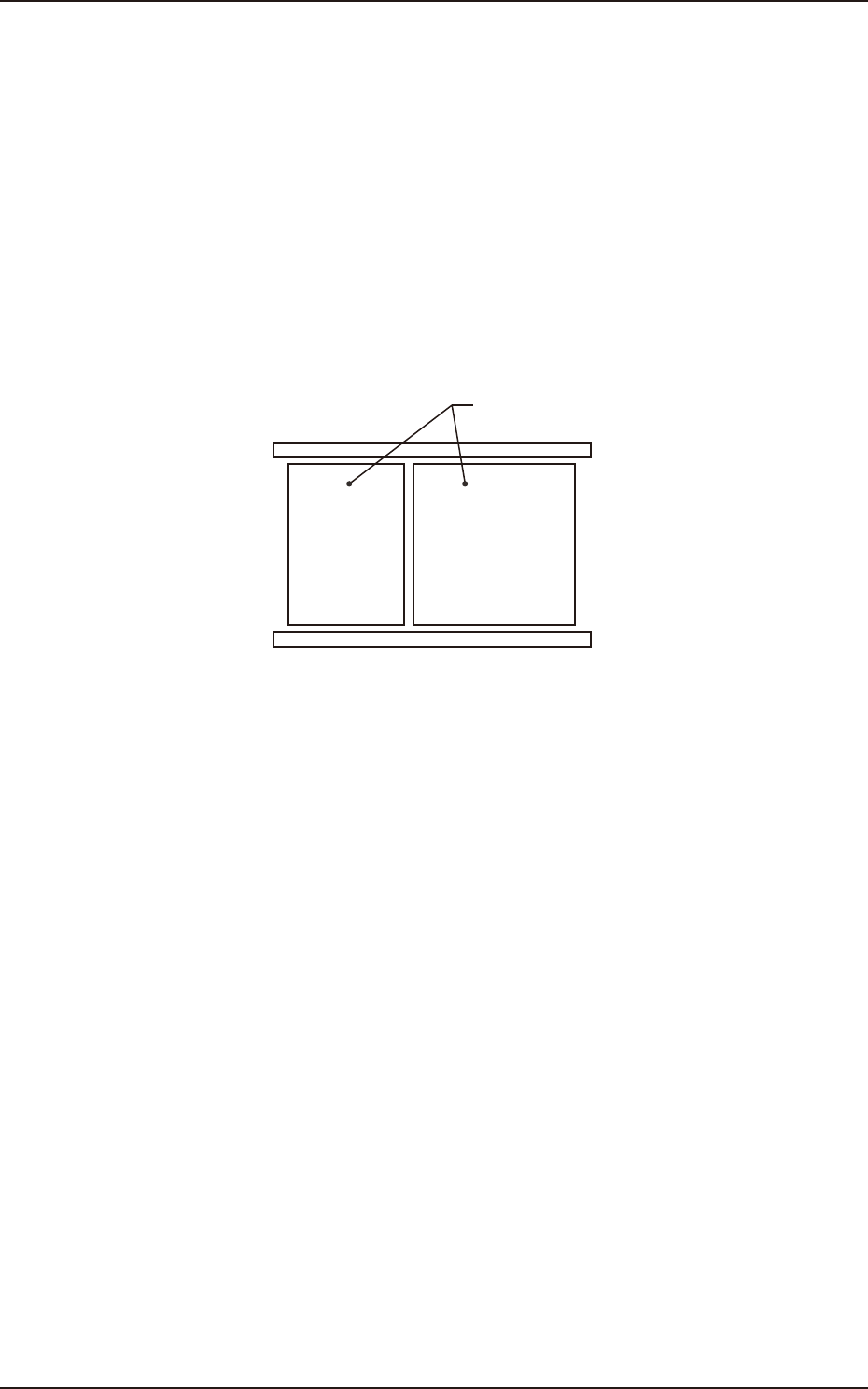
Table
Using this selection box, it is set that the backup base where the support pins are placed, is in the
output or input.
Input Output
Backup Base
F2B27
EUKYX
2-32199-2100
3.3 Operation
(C05_05)
M-X, M-Y
Using these selection boxes, the support pin placement coordinates (M-X, M-Y) are setup.
Coord X, Coord Y
The set support pin coordinates are displayed in these data boxes.
• Data Input Range
Input: M-X : 1 to 30 / M-Y : 1 to 50
Output: M-X : 1 to 30 / M-Y : 1 to 50
Y
X
Input Output
F2B28
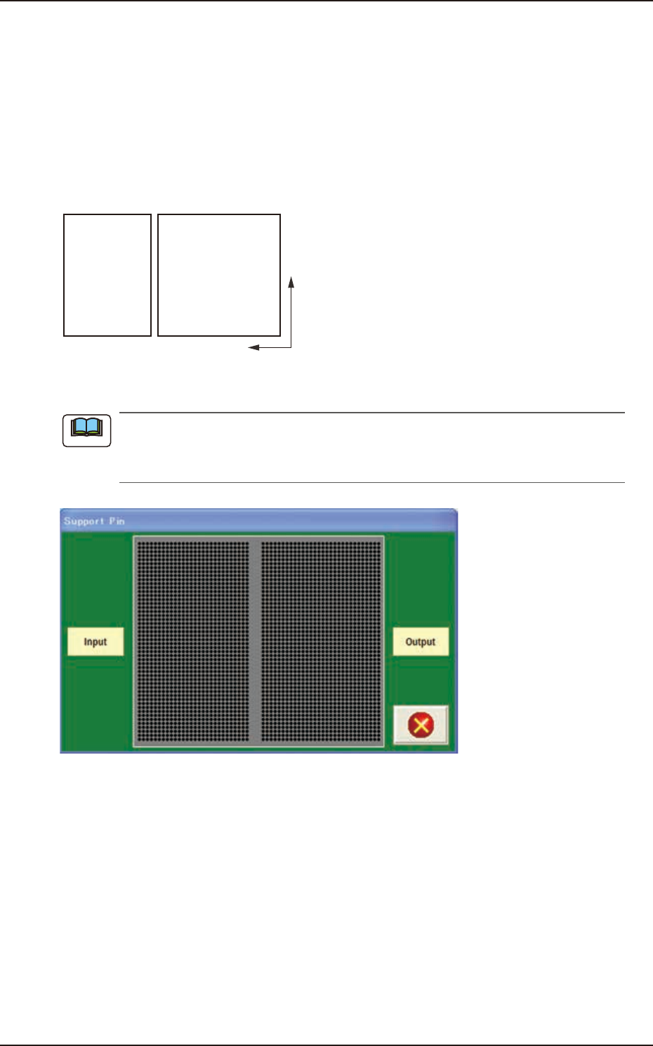
When the [Pin] button is pressed, the "Support Pin" dialogue box is opened and the support
pin positions can be checked.
When the [Clear] button is pressed, the support pins with the selected Nos. are cleared.
F2B29
Note