EUKYX-199-2100_G5S2_Instruction_Vol2_E.pdf - 第292页
EUKYX 6-55 199-2100 [ 7 ] This shows the coordinat e syste m of the comp onent librar y . When you c l ic k the coordin ate g raph ic and d rag the arm portion of the coordina te s, the whol e graph ic mo ves. Dra gging …
EUKYX
6-54199-2100
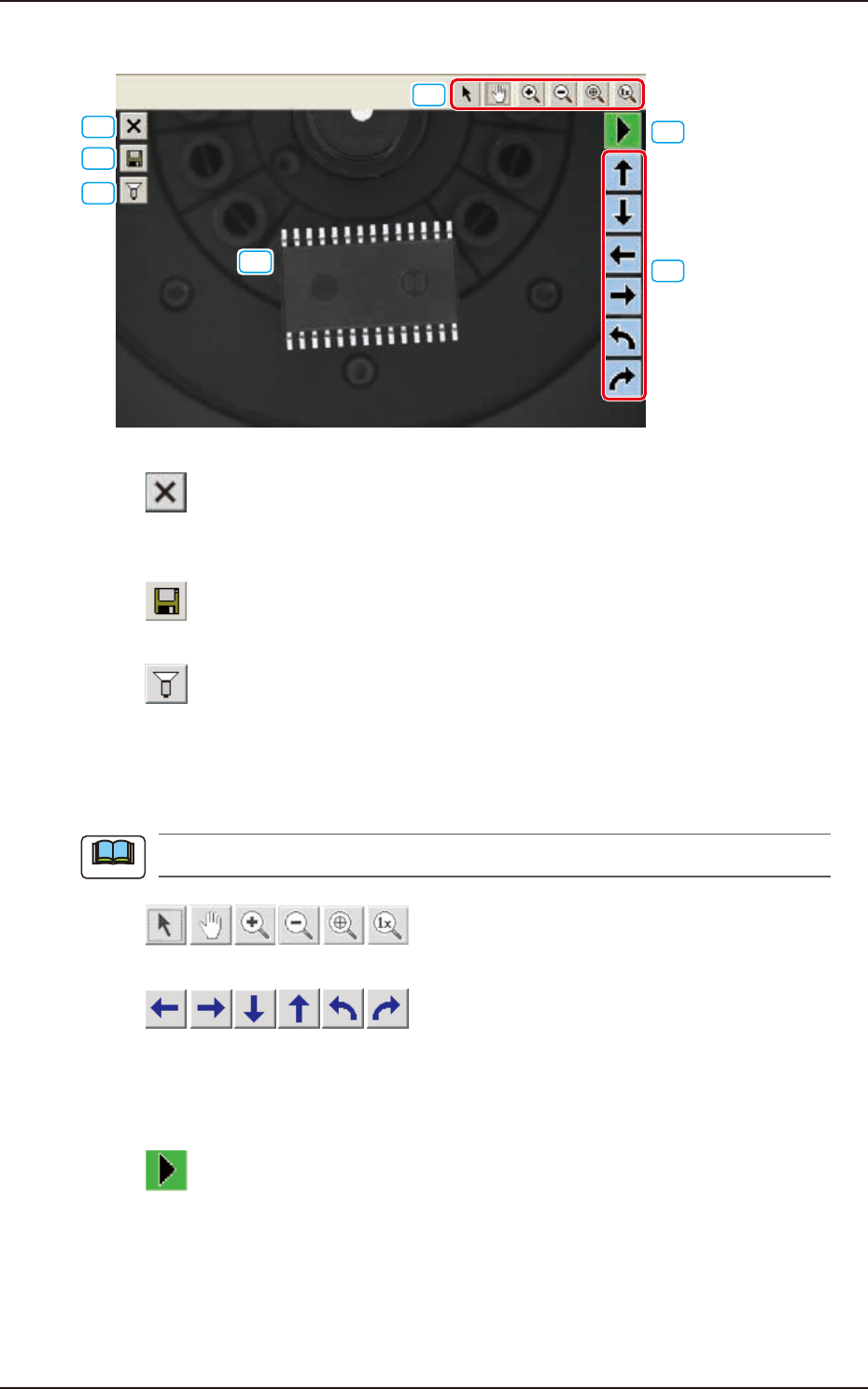
7.3.6.1 Explanation of "Component Library Teaching" Window
[1]
[2]
[3]
[4]
[5]
[6]
[7]
F2F57
[1] [ ] Button
Press this button to exit from the component library teaching session.
To save the edited data, press the [Yes] button. Pressing the [No] button aborts the data.
[2] [
] Button
This saves the edited data.
[3] [
] Button
This opens an image capture dialog box, making it possible to capture an image according to the
specified condition.
At the time of "New Teaching" or "Modification Teaching", the captured image is used for the
teaching operations.
The lighting pattern specified in this dialog box is not reflected on the library data.
[4] [
] Buttons
These buttons move the displayed image.
[5] [
] Buttons
When one of these arrow buttons is selected, the selected graphic moves or rotates slightly in the
selected direction.
When the coordinate system, the mold size, or the outward length is selected, the whole graphic
moves or rotates slightly in the selected direction.
[6] [
] Button
When this button is pressed the graphic image movement speed is changed.
Note
7.3 "COMP RCG" Test Window
EUKYX
6-55199-2100
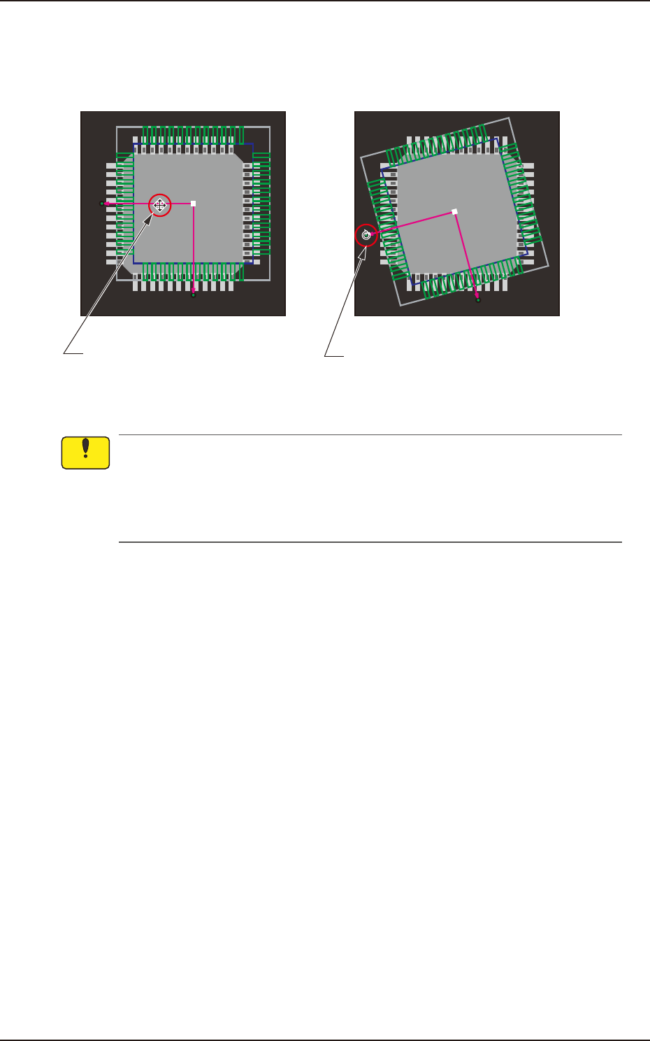
[7] This shows the coordinate system of the component library.
When you click the coordinate graphic and drag the arm portion of the coordinates, the whole
graphic moves. Dragging the end of the arrow mark of the coordinates makes the whole graphic
rotate.
Dragging the line segment of the
arrow extended from the coordinate
point moves the whole graphic.
Dragging the arrowhead rotates
the whole graphic.
F2F58
(a) The coordinate system of the component library is described as "Upper +" and "Right +"
in the instruction manuals, etc. However, as the image of a component is captured from
under the component, it should be noted that the direction of the X axis is reversed (Left +).
(b) Note that dragging a lead, an electrode, etc., other than a graphic coordinate segment
changes the component library data.
Notice
7.3 "COMP RCG" Test Window
EUKYX
6-56199-2100
[8]
[9]
[10]
[11]
[12]
[13]
[14]
[15]
[16]
[17]
F2F59
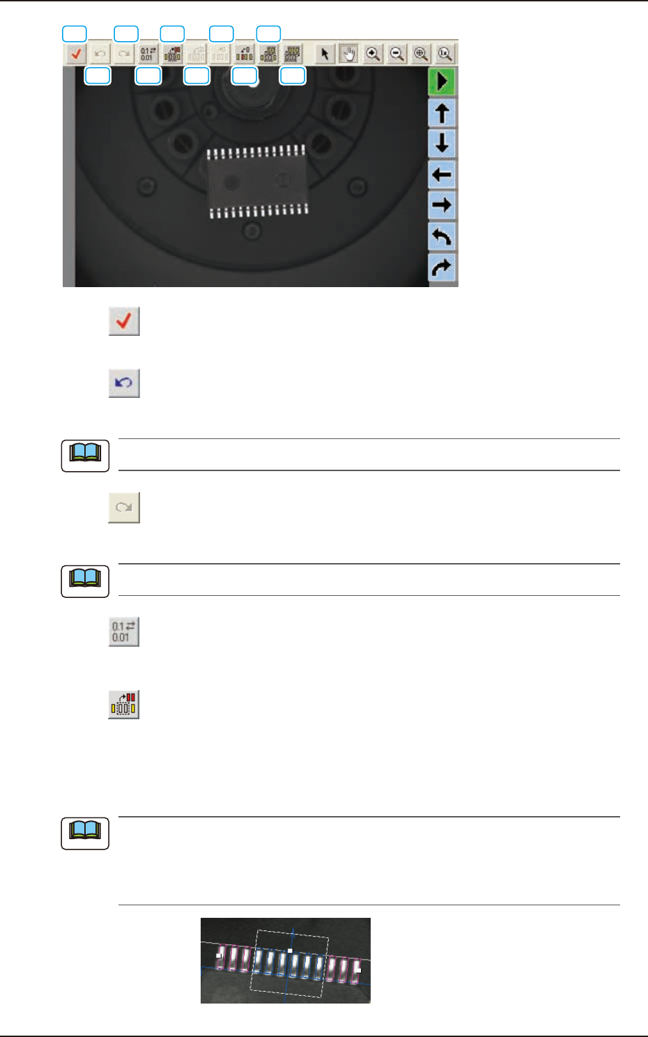
[8] [ ] Button
This checks the created library data.
[9] [
] Button
When this button is pressed, the previous library data item is back.
The component graphic image position is not returned.
[10] [
] Button
When this button is pressed, the previous library data item is returned.
The component graphic image position is not returned.
[11] [
] Button
This opens a data round-up dialog, making it possible to round up the data based on the specified
unit of measurement.
[12] [
] Button
This specifies the missing leads and balls. When you click the lead group or the ball group to be
selected as an object group for missing lead or ball detection, the color of the graphic squares changes
from “Green” to “Yellow”, indicating that this button has become valid. After clicking the button,
enclose the leaded portion to be specified as a missing area with the track ball as shown below.
When “IC (Simple)”, “Connector (Simple)”, or “Other Leaded (Simple)” is selected in the
“Component Shape” text box, one place can be specified for one group. In the case of “IC
(Complex)”, “Connector (Complex)”, or “Other Leaded (Complex)”, up to three places can be
specified. In the case of “BGA/CSP”, up to forty places can be specified.
F2F60
Note
Note
Note
7.3 "COMP RCG" Test Window