EUKYX-199-2100_G5S2_Instruction_Vol2_E.pdf - 第247页
EUKYX 6-10 199-2100 4.1 Collecting PCB Support Pins/Setting up Conveyor Width (4) Op en the cover and rem ove the suppo r t pins . (5 ) Close the c over . (6) Press the [Produ ct Opn Target P os M ovement] but ton. Withi…
EUKYX
6-9199-2100
4.1 Collecting PCB Support Pins/Setting up Conveyor Width
4.1 Collecting PCB Support Pins/Setting up Conveyor Width
• For Support Pin Manual Change
The PCB support pins are used to keep the upper surface of the PCB in proper height for
stabilization of the component placement. If the conveyor width is not correctly set, the PCB
support pins cannot be attached correctly.
When 0402 and 0603 components must be placed, it is important to secure the flatness of the
PCB. Use the support pins or a backup plate.
Contact YAMAHA sales representatives for how to make a backup plate.
CAUTION
The load power to the motors, etc., is turned
OFF but the setup operation must be performed
carefully when you put your hand inside the
machine. Avoid hand and nger injuries.
(1)
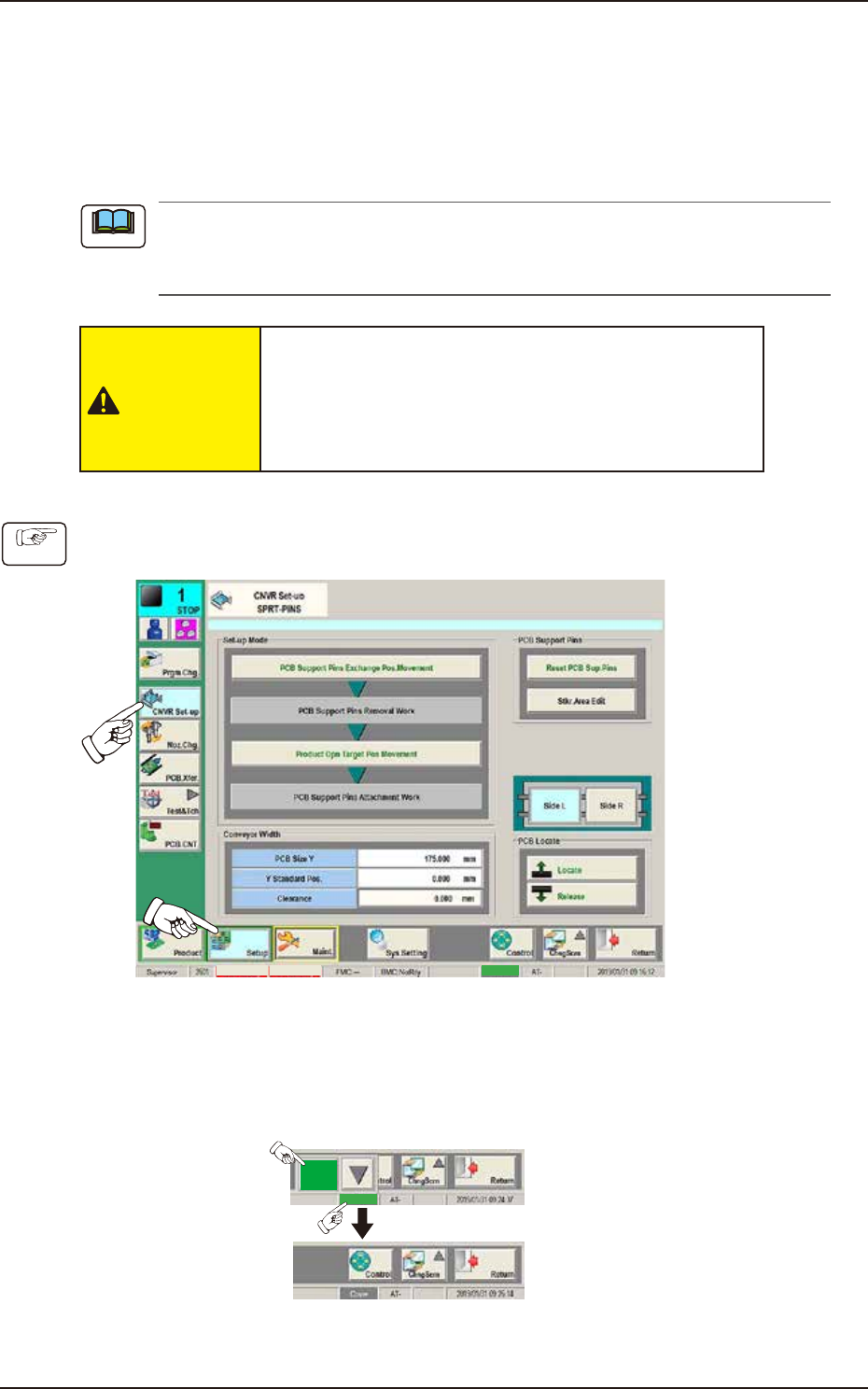
Press the [Setup] button and [CNVR Set-up] button to display the “CNVR Set-up SPRT-PINS“
window.
MTN:NotRdy RCG:NotRdy Cover
F2F10
(2)
Press the [PCB Support Pins Exchange Pos. Movement] button.
After that, press the [START] button on the operation panel within 10 seconds (The machine
retracts the head and maximizes the conveyor width.)
(3) Press the “cover” to unlock the cover.
Cover
Cover
F2F10A
Note
Procedure
EUKYX
6-10199-2100
4.1 Collecting PCB Support Pins/Setting up Conveyor Width
(4) Open the cover and remove the support pins.
(5) Close the cover.
(6)
Press the [Product Opn Target Pos Movement] button.
Within 10 seconds, press the [START] button on the operation panel.
(The conveyor width is changed appropriate for the selected pattern program.)
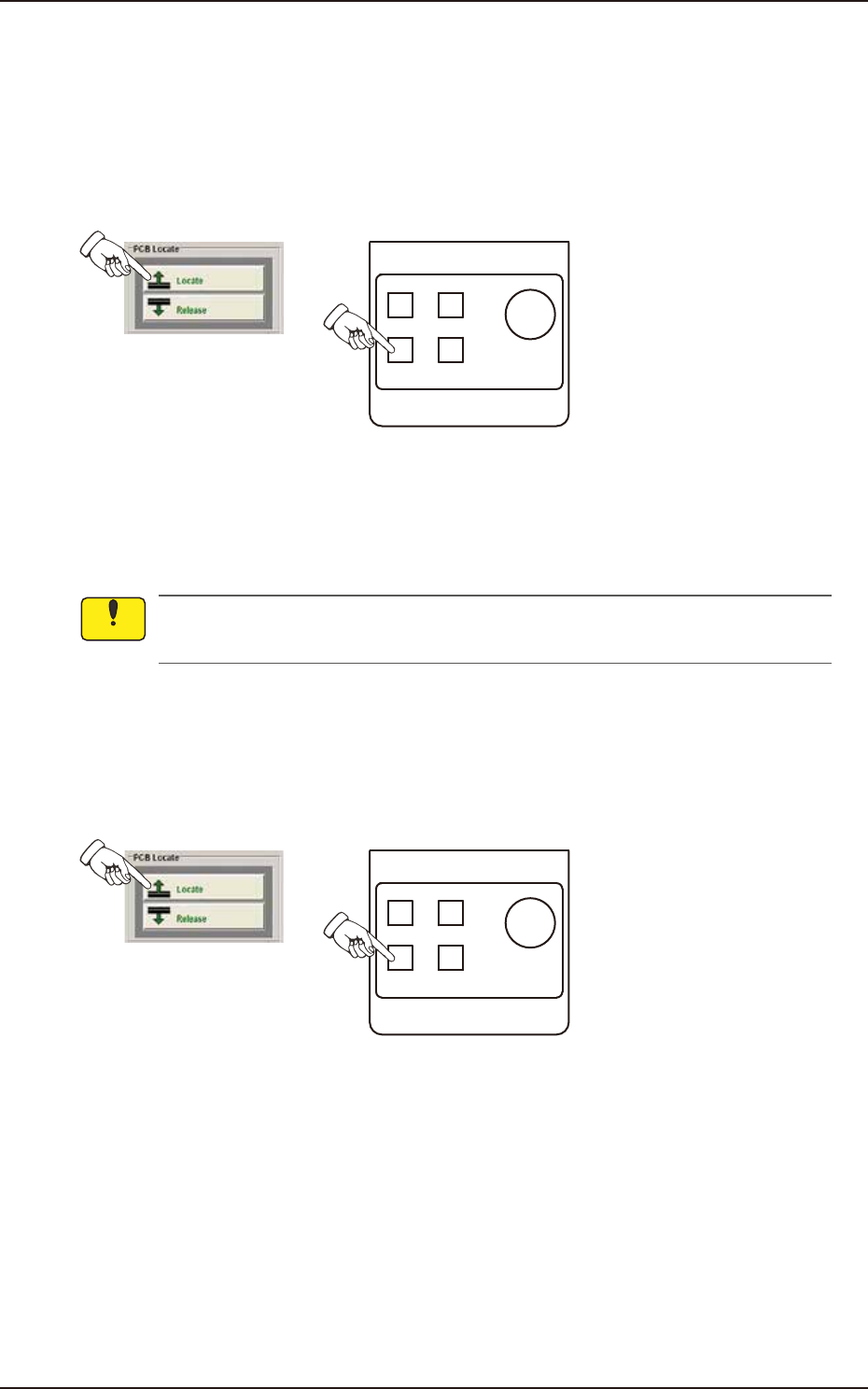
(7)
Press the [Locate] button in the “PCB Locate” group box and press the [START] button on
the operation panel within 10 seconds. (The backup base is moved up.)
POWER ON
STOP
PNL CHANGE
START
F2F10B
(8) Press the [COVER] button at the bottom of window to unlock the cover and open the cover.
(9)
Insert the PCB support pins vertically to the holes on the backup base.
(Be sure to set up the PCB support pins such that they are dispersed to support the object
PCB equally.)
Do not put your hand or any heavy object on the backup base while working on the backup
base. Otherwise, the backup base may be deformed due to an excessive load.
(10)
Confirm that a PCB support pin, etc., is not left behind on the backup base. (Confirm that
no component or dust, etc., has fallen into the holes on the backup base.)
(11) Close the cover .
(12)
Press the [Locate] button in the “PCB Locate” group box and press the [START] button on
the operation panel within 10 seconds. (The backup base is moved down.)
POWER ON
STOP
PNL CHANGE
START
F2F13
Notice
EUKYX
6-11199-2100
4.1 Collecting PCB Support Pins/Setting up Conveyor Width
• For Support Pin Automatic Change
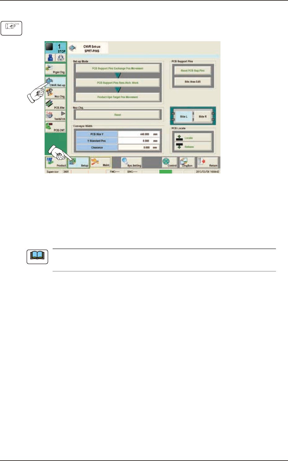
(1)
Press the [Setup] button and [CNVR Set-up] button to display the “CNVR Set-up SPRT-PINS“
window.
MTN:NotRdy RCG:NotRdy Cover
F2F12
(2)
Press the [PCB Support Pins Exchange Pos. Movement] button.
After that, press the [START] button on the operation panel within 10 seconds. (The
machine retracts the head and maximizes the conveyor width.)
(3)
Press the [PCB Support Pins Rem./Atch. Work] button and within 10 seconds, press the
[START] button on the operation panel.
(The support pin attachment or removal will be performed automatically).
When the support pins are to be changed automatically, prepare the nozzle (PK01) in the
nozzle stocker.)
(4)
Press the [Product Opn Target Pos Movement] button and within 10 seconds, press the
[START] button on the operation panel.
(The conveyor width will be changed according to the selected pattern program).
Procedure
Note