EUKYX-199-2100_G5S2_Instruction_Vol2_E.pdf - 第75页
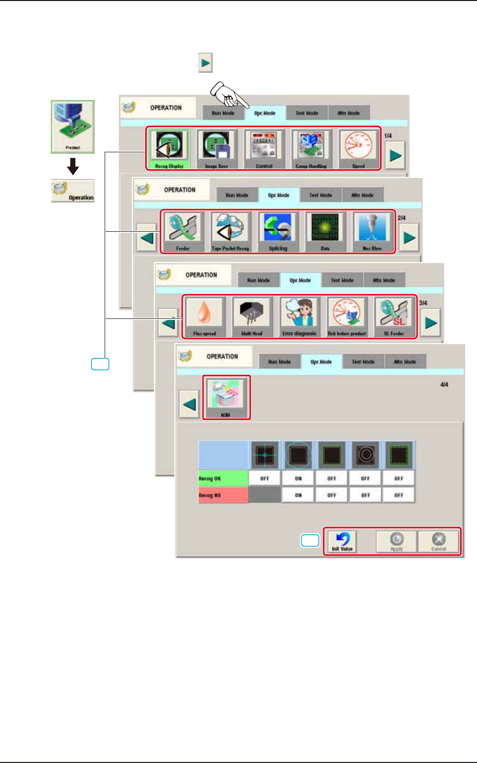
EUKYX 1-25 199-2100 4.2 "Opr .Mode" T ab Sheet 4.2 "Opr .Mode " T ab Sheet When the [ Opr . Mod e] t ab is pressed, the "Opr .Mo de" tab sheet (1 st page) appears a s an i ni tia l one. Ever…
EUKYX
1-24199-2100
4.1 "Run Mode" Tab Sheet
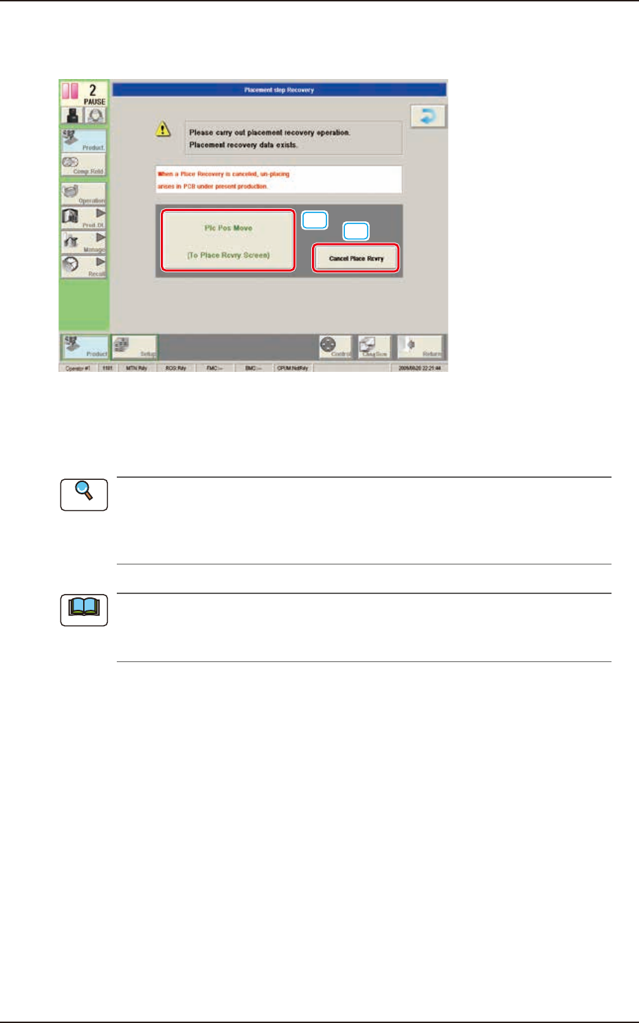
4.1.3 "Run Mode" Window in "Placement Recovery Available" Mode
"Enable" or "Disable" for the NL-axis Origin Teaching, is setup in this data box.
[1]
[2]
F2A22
[1] [Plc Pos Move] Button
When pressed, this button opens the "When the NL-axis origin teaching is to be performed, the
teaching time interval is selected from the following items." window.
A pre-pick nozzle confirmation error will not occur when the pre-pick nozzle confirmation
function is not used.
Refer to”4.2 “Opr.Mode” Tab Sheet” in "Chapter 1" for how to use the pre-pick nozzle
confirmation function.
When the machine is reset to its normal condition from the "ERROR" window after a pre-pick
nozzle confirmation error has occurred, the "Placement Step Recovery" window appears
automatically.
[2] [Cancel Place Rcvry] Button
When pressed, the placement recovery is cancelled.
Reference
Note
EUKYX
1-25199-2100
4.2 "Opr.Mode" Tab Sheet
4.2 "Opr.Mode" Tab Sheet
When the [Opr.Mode] tab is pressed, the "Opr.Mode" tab sheet (1st page) appears as an initial one.
Every time the Page switch button [ ] is pressed, 2,3, or 4 page in the “Opr.Mode” is displayed.
[1]
Graphic
Development
"Opr.Mode" Tab sheet (1/4 page)
2/4 page
3/4 page
4/4 page
[2]
F2A23A
[1] “Opr.Mode” Select
The setting is performed in this area for the selected button.
When the setting has been changed, press the [Apply] button to apply the setting.
[2] Common Button
[Init Value] Button
When pressed, the set condition parameters are returned to the initial values.
[Apply] Button
When pressed, the changed setting is applied.
[Cancel] Button
When pressed the changed setting is returned to the one prior to the change.
EUKYX
1-26199-2100
4.2 "Opr.Mode" Tab Sheet
4.2.1 Recog Display
When the [Recog Display] button is pressed on the "Opr.Mode" tab sheet, the following window appears.
On this window, the graphic display setting when the recognition results are displayed, is performed.
[1]
[2]
F2A26A
[1] Recog OK
When the result of recognition is normal, the graphics of the items for which the setting has
been "ON" using the following buttons, are displayed.
[Cross] Button
When selected, this displays a crosshair at the center of the recognized object.
[Circle] Button
When selected, this displays a circle at the center of the recognized object.
[Outside] Button
When selected, this displays the outline of the recognized object.
[Nozzle Outside] Button
When selected, this displays the outline of the vacuum nozzle that was used to recognize a
component.
[Detect Pos] Button
When selected, this displays the detection area, detected corner or edge position.
[2] Recog NG
When the result of recognition is abnormal, the graphics of the items for which the setting
has been “ON” using the following buttons, are displayed.
[Circle] Button
When selected, this displays a circle at the center of the recognized object.
[Outside] Button
When selected, this displays the outline of the recognized object.
[Nozzle Outside] Button
When selected, this displays the outline of the vacuum nozzle that was used to recognize a
component.
[Detect Pos] Button
When selected, this displays the detection area, detected corner or edge position.
When the button corresponding to the set item, is pressed, turning ON/OFF of the button can
be performed. Multiple items can be selected.
Note