EUKYX-199-2100_G5S2_Instruction_Vol2_E.pdf - 第320页
EUKYX 6-83 199-2100 7.4 "PEC RCG" T est Window 7 . 4. 1 Manua l Alignment Operation The PEC recogni tion posi tion i s located us in g the manu al a l ign ment operation . When the [ Manua l Alig nment] button …
EUKYX
6-82199-2100
7.4 "PEC RCG" Test Window
[5] [Move] Button
Using this button, the beam is moved to the set position.
[6] [Manual Alignment] Button
Using this button, the window where the recognition position setup using the manual alignment
operation, is opened.
[7] [PEC Recog] Button
When this button is pressed, the PEC recognition test is prepared.
[8] Result:
In this pane, the PEC recognition test results are displayed.
[9] [PCB XFER] Button
When this button is pressed, the "PCB Transfer" window appears.
See “6. “PCB XFER” Window” in this chapter for details.
[10] [Save Image] Button
When this button is pressed, the "Image Save" window appears.
This window is used to save the test results.
[11] [
(Re-Recognition)] Button
After pressing this button, the recognition image is touched in the "Manual Alignment" window to
re-recognize the marks.
Reference
EUKYX
6-83199-2100
7.4 "PEC RCG" Test Window
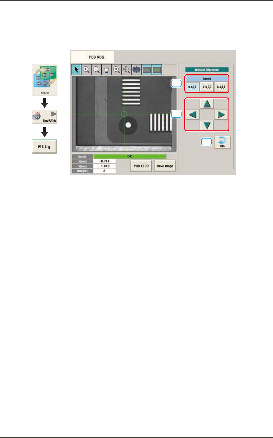
7.4.1 Manual Alignment Operation
The PEC recognition position is located using the manual alignment operation.
When the [Manual Alignment] button is pressed after the [Move] button is pressed on the "PEC
RCG" test window, the "Manual Alignment" window appears.
[1]
[2]
[3]
Graphic
Development
F2F117
[1] [Speed] Button
The beam movement speed in the manual alignment operation is selected from the following items.
[0.5 mm] Button, [2.0 mm] Button, [5.0 mm] Button
[2] [Arrow] buttons
When pressed, the direction to move the beam is specified.
Press the button and then press the [START] button within 10 seconds. The beam is moved at the
speed selected in "[1] Speed Setup" in the arrow direction.
[3] [Rtn] Button
When pressed, the window returns to the "PCB Test" window.
EUKYX
6-84199-2100
7.4 "PEC RCG" Test Window
7.4.2 PEC Recognition Test Procedure
• PEC Recognition Test Preparation
(1) Open the "PP CHANGE" window from the "Setup" main menu to set the pattern program.
(2) Transfer the PCB to be tested onto the PCB positioning section on the "PCB XFER" window
selected from [Setup] menu or "PCB XFER" window displayed by pressing the [PCB XFER]
button on the "PEC RCG" test window.
(3) Press the [Mark Pos Edit] on the “PEC RCG” window to display the “Mark Pos. Edit“
window. Set the PEC recognition mark on the window.
Press the [Mark Data Edit] button on the “PEC RCG” window to display the “Mark Data
Edit“ window. Set each parameter for the PEC recognition mark.
Selecting [Zone n] and [#n] for the global recognition position in the [Set Data (Crnt.PP.)]
window, can set the position data and PEC recognition mark code.
(4) Move the XY beam so that the PEC recognition mark with which the PEC recognition test is
performed, is within the recognition range (camera view).
For the XY beam movement operation, there are two ways; one is "Move", that is a method to
move to the position set on “[Set Data (Crnt. PP.)] window“. The other one is "Manual Alignment
Operation" where the recognition window is displayed and the XY beam position is adjusted
using the manual alignment operation, viewing the recognition image.
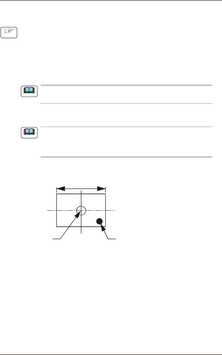
Locate the recognition mark close to a corner of the recognition range as shown in the following
figure.
Center of the
Recognized Image
Recognition Mark
Recognition Range
F2F118
Procedure
Note
Note