X3_X4_Series machine.pdf - 第115页
User manual SIPLAC E X-Series 3 Technical data Software Vers ion SR.601.xx 11/ 2005 US Ed ition 3.5 Line concept 115 3.5.2 SIPLACE set-up optimization The SIPL ACE set-up o ptimizat ion incr eases the producti vity of yo…
3 Technical data User manual SIPLACE X-Series
3.5 Line concept Software Version SR.601.xx 11/2005 US Edition
114
3.5 Line concept
3.5.1 Description
3
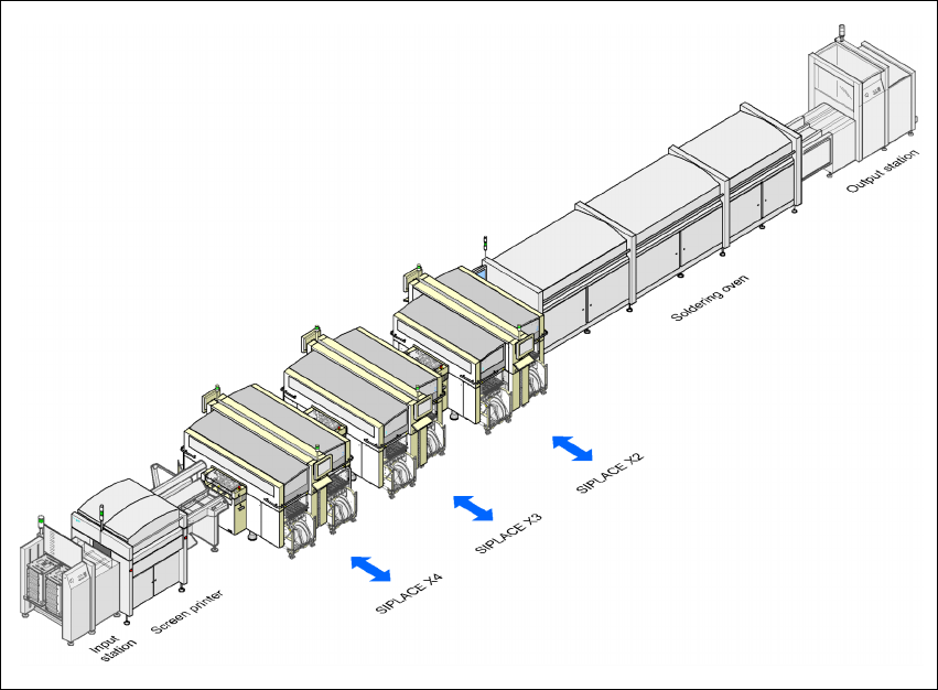
The SIPLACE concept is characterized by its flexibility, modularity, compactness and high power
density. It allows a production line to be individually configured from identical and different mod-
ules. If the production requirements change, the individual placement machines are so compact
that they can be recombined quickly and easily.
3
Fig. 3.5 - 1 Sample line concept
3
The SIPLACE family has exactly the right placement machine, whatever the output requirements:
SIPLACE X-series
placement machines can be used to place IC, flip-chip, bare die and
exotic components (OSC). They cover the spectrum of components from 0201 to 85 x 85 /
125 x 100 mm² with a very high placement rate.
User manual SIPLACE X-Series 3 Technical data
Software Version SR.601.xx 11/2005 US Edition 3.5 Line concept
115
3.5.2 SIPLACE set-up optimization
The SIPLACE set-up optimization increases the productivity of your line since it minimizes place-
ment times and non-productive times for your placement machines. The set-up software calcu-
lates individual set-ups for individual products, individual set-ups for different products and family
set-ups for different products. The program data can be exchanged between the individual lines -
even for different machine configurations.
3 Technical data User manual SIPLACE X-Series
3.6 Overview of the modules Software Version SR.601.xx 11/2005 US Edition
116
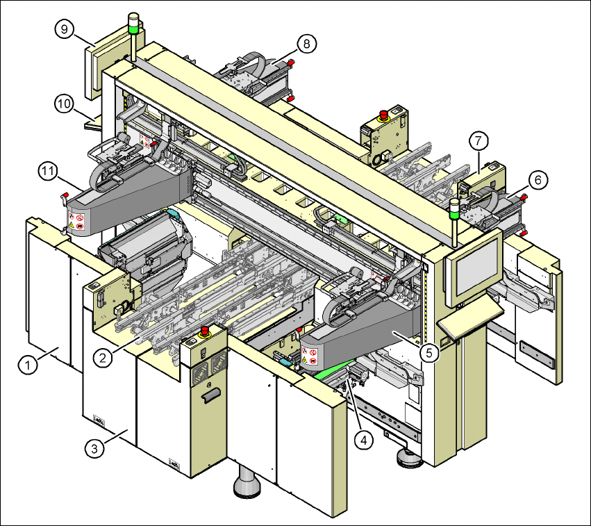
3.6 Overview of the modules
3
Fig. 3.6 - 1 X4 machine - protective covers and covers
(1) Machine frame
(2) PCB conveyor (flexible dual conveyor)
(3) Extension kit on the PCB input side
(4) Component trolley docking unit, tape cutter, used tape channel (4x)
(5) Gantry 1 with placement head (X4, X3 and X2)
(6) Gantry 2 with placement head (X4)
(7) Extension kit on the PCB output side
(8) Gantry 3 with placement head (X4, X3 and X2)
(9) Monitor (2x)
(10) Keyboard (2x)
(11) Gantry 4 with placement head (X4 and X3)