X3_X4_Series machine.pdf - 第127页
User manual SIPLAC E X-Series 3 Technical data Software Vers ion SR.601.xx 11/ 2005 US Ed ition 3.7 Placem ent heads 127 3.7.2.4 T echnical dat a 3 *) Smaller c omponents, e.g. 01005, available on r equest Please note th…

3 Technical data User manual SIPLACE X-Series
3.7 Placement heads Software Version SR.601.xx 11/2005 US Edition
126
air is taken in at one or more nozzle, the segments will not be affected and can continue place-
ment.
At the "Vacuum check" star position (item 10 in Fig. 3.7 - 6
), the current vacuum value of a seg-
ment can be measured in the holding circuit with or without component.
Component sensor (item 5 in Fig. 3.7 - 5) 3
The component sensor is positioned so that components can be measured at the pick-up/place-
ment position (item 1 in Fig. 3.7 - 6
). Measurements at the tip of the nozzle can thus be carried
out during every Z axis movement. Differential measurements can be used to identify components
missing from the nozzles. The component height can also be detected.
Component camera (item 1 in Fig. 3.7 - 5) 3
The component camera is mounted on the placement head at star position 11 (item 11 in Fig. 3.7
- 6). It uses a digital interface (hotlink) to exchange data with the vision processor in the axis unit.
The camera is designed to capture the component from underneath. If a component drops onto
the camera, it is removed from the camera field via a removal ramp.
Adapter board (item 2 in Fig. 3.7 - 5) 3
The adapter board is the interface between placement head and placement machine. The vacuum
sensor for the holding circuit is mounted on the star housing.
The following functions are implemented on the adapter board:
– Display the operating voltages at the head
– Display the sensor statuses
– Test access to the CAN bus for the placement head
– Test connector for the signals from the incremental encoder
– Test pins for the analog signals
– Control of the power supply for the incremental encoders for the star and Z drives
– SPI bus interface for the component sensor, the vacuum unit, the "Holding circuit" vac-
uum sensor and the EEPROM
– Signal processing for the output signal from the "Holding circuit" vacuum sensor
– Signal processing for the component sensor signal
– Signal processing for the "Z axis down" sensor
– Signal processing for the CAN bus for the placement head and the machine
– Activation of the return cylinder for the Z axis

User manual SIPLACE X-Series 3 Technical data
Software Version SR.601.xx 11/2005 US Edition 3.7 Placement heads
127
3.7.2.4 Technical data
3
*) Smaller components, e.g. 01005, available on request
Please note that the component range that can be placed is also affected by the pad geometry, the cus-
tomer-specific standards and the packaging tolerances.
3
3
3
3
3.7.2.5 Sensor for the component reject bin
PLEASE NOTE 3
If a 20-segment Collect&Place head is used, then the sensor for the component reject bin is
absolutely essential. (See also section 7.2 from page 410 onwards.)
Range of components 0201
*)
to 2220, Melf, SOT, SOD
Component specification
Max. height
Min. lead pitch
Min. ball pitch
Min. ball diameter
Min. dimensions
Max. dimensions
Max. weight
4 mm
0.3 mm
0.4 mm
0.2 mm
0.2 x 0.2 mm²
6 x 6 mm²
1 g
Programmable set-down force, variable increments 2.0 ± 0.5 N
3.5 ± 1 N
4.5 ± 1 N
Nozzle types 10xx, 11xx, 12xx
X/Y accuracy ± 41 µm/3 σ, ± 55 µm/4 σ
Angular accuracy ± 0.5°/3 σ, ± 0.7°/4 σ
3 Technical data User manual SIPLACE X-Series
3.7 Placement heads Software Version SR.601.xx 11/2005 US Edition
128
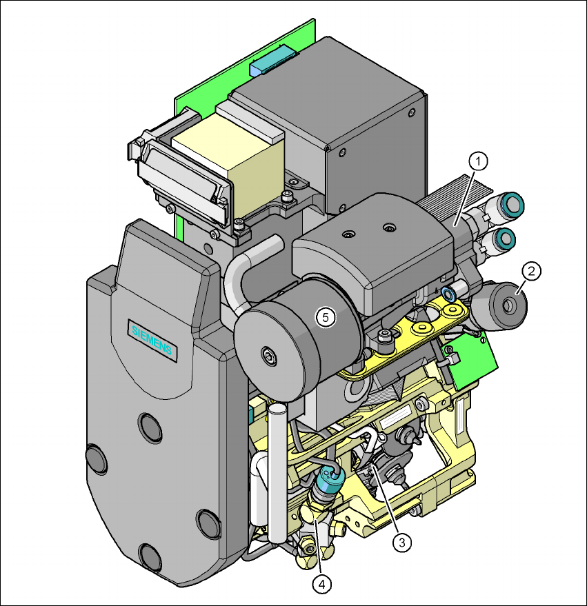
3.7.3 12-segment Collect&Place head for high-speed placement
3
Fig. 3.7 - 7 12-segment Collect&Place head - Function groups, part 1
3
(1) Vacuum generator
(2) Turning station, DP axis
(3) Star with 12 sleeves, star axis
(4) Forced air valve
(5) Silencer