X3_X4_Series machine.pdf - 第69页
User manual SIPLAC E X-Series 2 Operational safety Software Vers ion SR.601.xx 11/ 2005 US Ed ition 2.6 Safety equipment 69 Protective contact or combination 3TK2806 (item 1 in Fig. 2.6 - 6 ) 2 The pro tective contactor …
2 Operational safety User manual SIPLACE X-Series
2.6 Safety equipment Software Version SR.601.xx 11/2005 US Edition
68
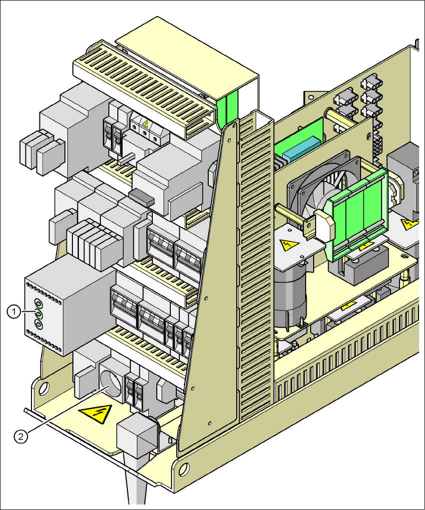
2.6.3 Position of protective contactor combination and service socket
2
Fig. 2.6 - 6 Position of protective contactor combination and service socket
2
(1) Protective contactor combination
(2) Service socket
User manual SIPLACE X-Series 2 Operational safety
Software Version SR.601.xx 11/2005 US Edition 2.6 Safety equipment
69
Protective contactor combination 3TK2806 (item 1 in Fig. 2.6 - 6) 2
The protective contactor combination is contained in the power supply unit. It is used to monitor
the emergency stop circuits and safety equipment.
There are three conditions that must be fulfilled in order to activate the protective contactor com-
bination:
– The "software enable" signal must have been sent.
– The emergency stop loop must be closed.
– The Start button must have been pressed.
On the front panel of the protective contactor combination, there are three green operating display
LEDs (see Fig. 2.6 - 7
, page 70):
– The "Mains" LED indicates that voltage is present.
– The "Channel 1" and "Channel 2" LEDs light up if the Start button was pressed, the emer-
gency stop loop is closed and the signaling circuit is not signaling a fault status.
Service socket (item 2 in Fig. 2.6 - 6) 2
The service socket is contained in the power supply unit and is protected by the cover. It can only
be used if the placement system is connected to the main power supply via a 5-wire connection
(L1, L2, L3, N, and PE). If a 4-wire connection is used, e.g. without N, the socket cannot be used.
WARNING 2
Always follow the safety instructions concerning potentially lethal voltages - even when the
placement system is switched off. (See Section 2.1.5 from page 29 onwards.)
2 Operational safety User manual SIPLACE X-Series
2.6 Safety equipment Software Version SR.601.xx 11/2005 US Edition
70
2.6.4 Emergency stop loops and signaling circuit
2.6.4.1 Structure of the emergency stop loops
The following contacts are connected in series and form the emergency stop loop:
– normally open (NO) contacts for the four protective cover switches
– normally open (NO) contacts in the two protective switches for the cover flaps over the PCB
conveyor
– normally open (NO) contacts for the two emergency stop buttons
– normally open (NO) contacts for the feeder module cover flaps (option)
– normally open (NO) contacts for the four component trolleys
– channels of the PCC K6 protective contactor combination
With emergency stop loop 2, the CAN bus signal from the signaling circuit (see Section 2.6.4.2
)
is supplied to channel 2 of the protective contactor combination PCC K6. If the emergency stop
loop is closed, and the signaling circuit is not signaling a malfunction, then the two green LEDs for
channels 1 and 2 light up, in addition to the green mains power check LED of the protective con-
tactor combination.
2
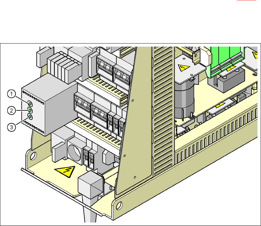
Fig. 2.6 - 7 Signal LED on the protective contactor combination
(1) Netz / Power
(2) Kanal 1 / Channel 1
(3) Kanal 2 / Channel 2