X3_X4_Series machine.pdf - 第347页
User manual SIPLAC E X-Series 6 Component han dling Software Version SR.601.xx 11/2005 US Edition 6.6 S feeder modules for the SIPLACE HF component trolley 347 PLEA SE NOT E – The wafflepack tra y holder c an be set up a…
6 Component handling User manual SIPLACE X-Series
6.6 S feeder modules for the SIPLACE HF component trolley Software Version SR.601.xx 11/2005 US Edition
346
6.6.3 Waffle-pack tray holder for the SIPLACE HF component trolley
The waffle-pack tray holder allows components to be picked up from individual waffle-pack trays.
The waffle-pack trays are changed manually. 6
6
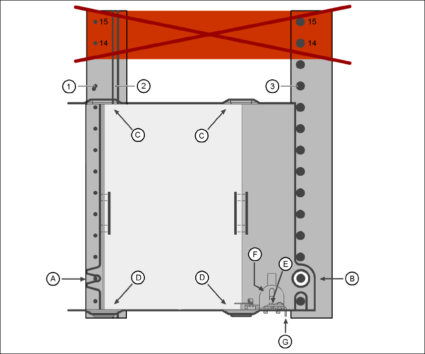
Fig. 6.6 - 16 Installation
(1) Centering pins
(2) Magnetic rail
(3) Centering ball
(14), (15) This position must not be filled.
6
The waffle-pack tray holder is placed on the component table as for a feeder module. There are
two different versions of the holders. The only difference is the width. 6
Holder for large waffle tray (260x360mm², fills 9 locations)
item no. 00116430-01 and 6
Holder for small waffle tray (136x360mm², fills 5 locations)
item no. 00116432-01 6
User manual SIPLACE X-Series 6 Component handling
Software Version SR.601.xx 11/2005 US Edition 6.6 S feeder modules for the SIPLACE HF component trolley
347
PLEASE NOTE
– The wafflepack tray holder can be set up at the following locations:
X2 machine: Locations 2 and 4
X3 machine: Location 2
Feeder module positions 14 and 15 on the component table must
not
be filled.
– The holder and the nozzle changer cannot be used at the same time at location 4.
– The component trolley cannot be docked in/out while the holder is fitted.
6.6.3.1 Assembly
Æ Insert the front side of the waffle-pack tray holder into the associated centering pin (A in Fig.
6.6 - 16
).
Æ Then position the hole on the rear side of the waffle-pack tray holder onto the centering ball on
the component feeder table (B in Fig. 6.6 - 16
).
Æ Make sure the waffle-pack tray is resting securely on the component feeder table.
Æ Position one side of the waffle-pack tray carrier in the mounting (C in Fig. 6.6 - 16). Then press
the other side into the mounting (D in Fig. 6.6 - 16
).
Æ Slide the waffle-pack tray up against the stop (E in Fig. 6.6 - 16).
Æ Secure the waffle-pack tray carrier by pressing the thrust pad (F in Fig. 6.6 - 16) downwards.
Æ To remove the waffle-pack tray carrier, press the thrust pad once more.
PLEASE NOTE
Using the holder for small waffle-pack trays (136mm) a waffle-pack tray (JEDEC or CENELEC
waffle-pack tray) can be fitted directly to the holder, in other words, without a waffle-pack tray car-
rier being used. However, the thrust pad will require changing. 6
WARNING 6
All locations must be equipped with feeder modules in order to guarantee operational reliability.
If there are not enough feeder modules available, unassigned locations should be fitted with a
hand guard (dummy feeder module). When a waffle-pack tray holder is set up, the remaining
locations have to be protected again with a hand guard.
6 Component handling User manual SIPLACE X-Series
6.6 S feeder modules for the SIPLACE HF component trolley Software Version SR.601.xx 11/2005 US Edition
348
6.6.3.2 Changing the retainer
Æ Hold the retainer (G in Fig. 6.6 - 16) firmly. Press the thrust pad downwards (F in Fig. 6.6 - 16)
and remove the retainer by pressing it out sideways.
6.6.3.3 Data entry
Define the waffle-pack trays as described in the SIPLACE Pro operating instructions. 6
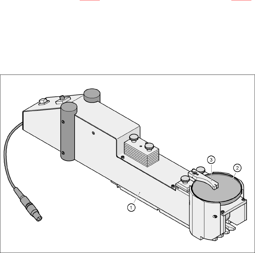
6.6.4 Dip module for the SIPLACE HF component trolley
6
Fig. 6.6 - 17 Dip module
(1) Dip module
(2) Rotating plate
(3) Squeegee
6.6.4.1 Principle of dip fluxing
The dip module (item 1) is used to wet flip-chip and CSP components with flux or conductive ad-
hesive. The flux holder is a rotating plate (item 2) on which a thin film of flux (e.g. 40 µm) is created
with a squeegee (item 3). This method is particularly suitable for highly viscous (honey-like) fluxes.