X3_X4_Series machine.pdf - 第257页
User manual SIPLAC E X-Series 5 Tasks on the machine Software Vers ion SR.601.xx 11/ 2005 US Ed ition 5.4 Setting up the feeder m odules 257 5.4 Settin g up the feed er modules 5.4.1 Notes on handling feeder modules Feed…
5 Tasks on the machine User manual SIPLACE X-Series
5.3 Carrying out a walk-through inspection Software Version SR.601.xx 11/2005 US Edition
256
5.3.7 Using spindles for large tape reels
Æ Insert spindles into the separating plates when using large tape reels.
PLEASE NOTE 5
We recommend that you use spindles if the tape reel diameter exceeds 15" (381 mm)". This will
ensure that the feeder modules operate reliably.
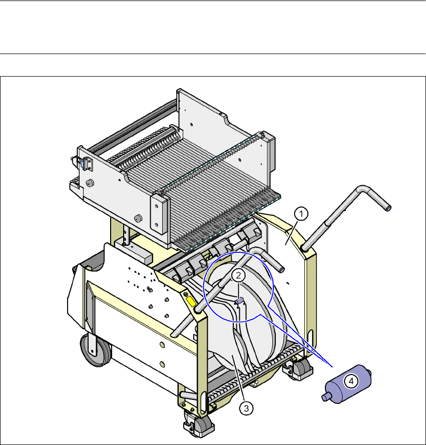
Fig. 5.3 - 5 Inserting spindles for large reels
5
(1) Tape container
(2) Position of the spindles
(3) Separating plate
(4) Spindle (enlarged)
User manual SIPLACE X-Series 5 Tasks on the machine
Software Version SR.601.xx 11/2005 US Edition 5.4 Setting up the feeder modules
257
5.4 Setting up the feeder modules
5.4.1 Notes on handling feeder modules
Feeder modules are precision devices. You should therefore handle the feeder modules with care.
Æ Avoid bumping feeder modules into obstacles.
Æ Do not drop the feeder modules.
Æ Always use suitable tools for preventive maintenance.
5.4.2 Removing X feeder modules from the component table
5
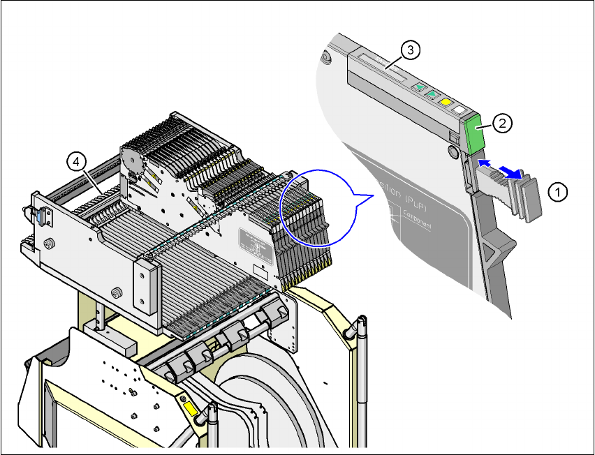
Fig. 5.4 - 1 Removing X feeder modules from the component table
(1) Removal handle
(2) Status display
(3) LCD display
(4) Latch for locking the X feeder modules

5 Tasks on the machine User manual SIPLACE X-Series
5.4 Setting up the feeder modules Software Version SR.601.xx 11/2005 US Edition
258
On standby, the status display (item 2 in Fig. 5.4 - 1) lights up green if the X-axis feeder module
is contained in the current set-up. If the feeder module is not contained in the current set-up, the
status display remains off.
The X feeder module is locked in position in the component table by a latch, and cannot be pulled
out. The procedure for removing feeder modules from the component table is as follows:
Æ Press the removal handle (item 1 in Fig. 5.4 - 1). The removal handle jumps out and the
status display goes out.
Æ Wait approximately 1 sec until the lock (item 4 in Fig. 5.4 - 1) releases the feeder module.
Æ Use the removal handle to pull the feeder module out of the component table. If you wait
longer than 5 seconds, the feeder module will be locked once more. The status display
lights up red and the message "Handle --->>" appears on the LCD display (item 3 in Fig.
5.4 - 1
).
Æ Engage the removal handle once more. If the X feeder module is contained in the current
set-up, the status display lights up green and the track number and increment are appear
on the LCD display once more.
Æ Press the removal handle again (item 1 in Fig. 5.4 - 1) and now pull the feeder module
out of the component table.
5.4.3 Using the X feeder module on the component trolley (X-series)
5.4.3.1 Checking the X feeder module before using it
Check the following points before you use a feeder module on the component table:
Æ The feeder module must be in perfect condition.
Æ Tap the cover foil rocker (item 2 in Fig. 5.4 - 2) lightly to make sure that it is not jammed.
Æ Check that the area around the pick-up window (item 3 in Fig. 5.4 - 2) is free from loose
components.
PLEASE NOTE 5
Empty the component disposal compartment (item 5 in Fig.5.4 - 2
) before you shake compo-
nents out of the feeder module.
Æ Push the lever (item 4 in Fig. 5.4 - 2) forward slightly to open the pick-up window (item 3
in Fig. 5.4 - 2
). This will raise the pick-up window slightly.
PLEASE NOTE 5
Do not press the lever if a component tape is inserted. The tensioned cover foil would move
the component tape on and expose the components.