X3_X4_Series machine.pdf - 第232页
4 Setting up and commissioning User manual SIPLACE X-Series 4.4 Setting up the placement machine Software Version SR.601.xx 11/2005 US E dition 232 4.4.15 Integrat ing the pl acement machi ne into th e line Æ Note the wa…
User manual SIPLACE X-Series 4 Setting up and commissioning
Software Version SR.601.xx 11/2005 US Edition 4.4 Setting up the placement machine
231
4
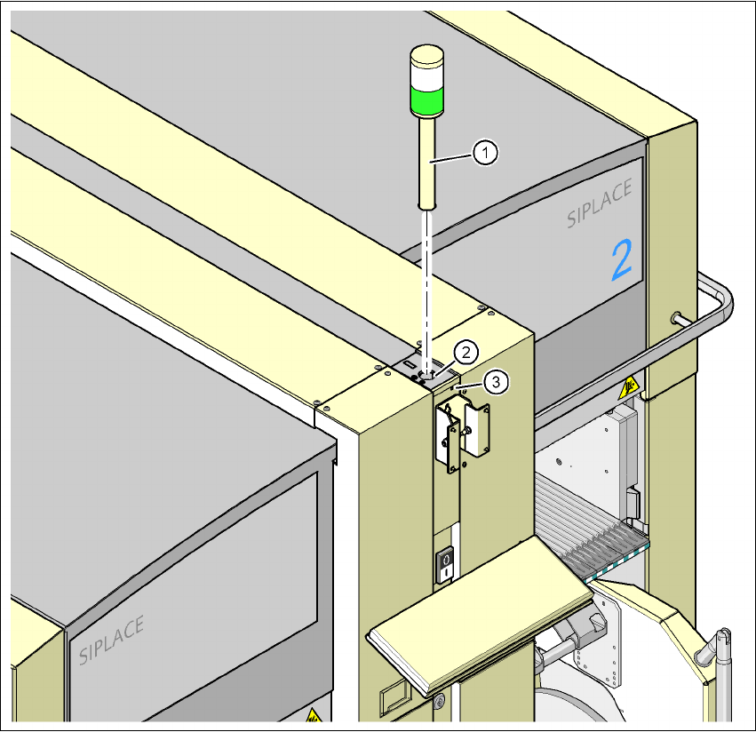
Fig. 4.4 - 23 Fitting the main indicator lamp
4
(1) Main indicator lamp
(2) Hole for the main indicator lamp
(3) Hole for the locking screw
4.4.14 Fixing the monitors
Æ Fix the monitors and connect the cables.
Æ Check the cable connections
4 Setting up and commissioning User manual SIPLACE X-Series
4.4 Setting up the placement machine Software Version SR.601.xx 11/2005 US Edition
232
4.4.15 Integrating the placement machine into the line
Æ Note the warning instructions described in section 4.4.2, page 190.
Æ The tools and equipment are listed in section 4.4.1, page 190.
4.4.15.1 Positioning the fork-lift
4
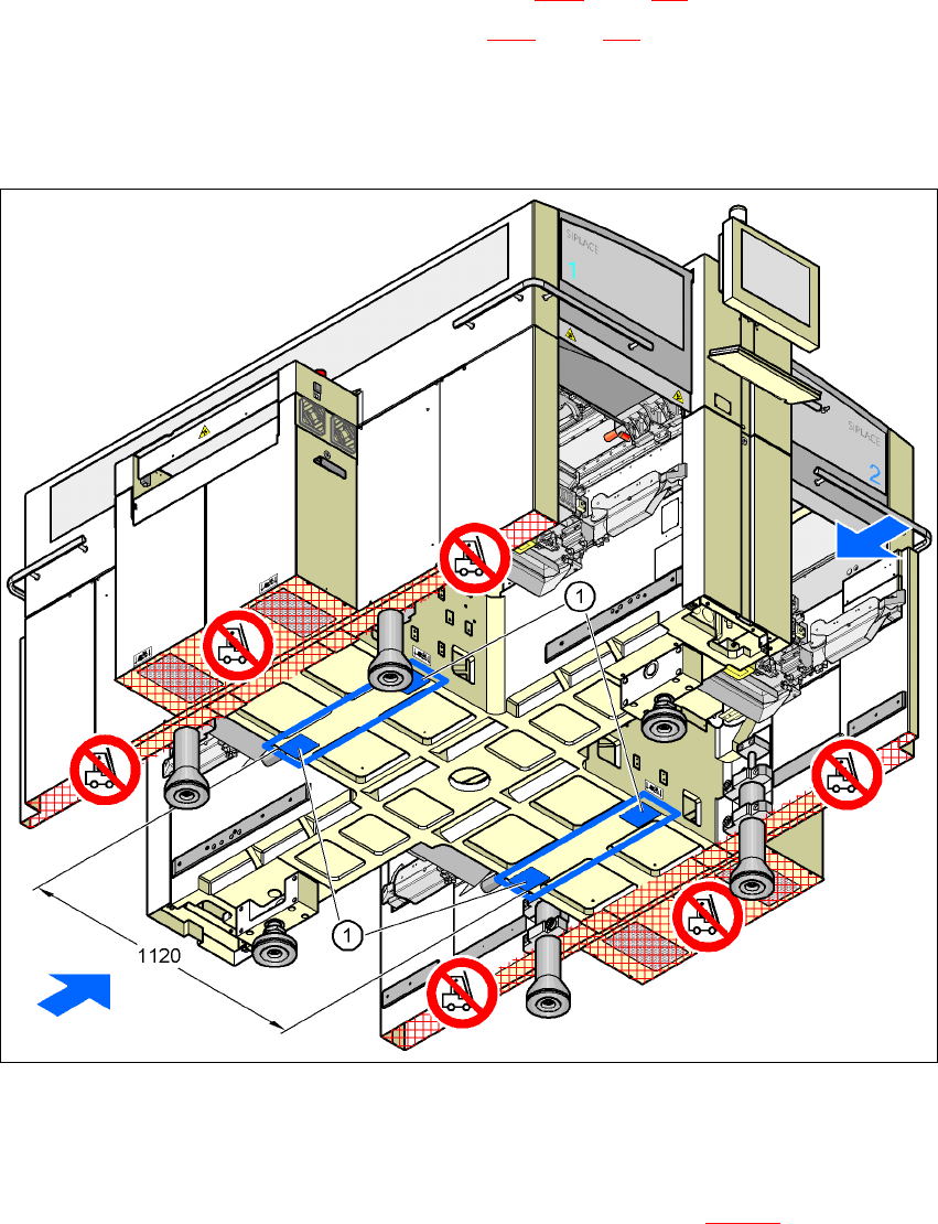
Fig. 4.4 - 24 Contact surfaces - Forks across the direction of PCB transport
(1) Contact surfaces for the forks of the fork-lift
Æ Position the fork-lift across the direction of PCB transport and open the forks far enough so
that the machine's contact surface lies evenly on the forks (see Fig. 4.4 - 24
).

User manual SIPLACE X-Series 4 Setting up and commissioning
Software Version SR.601.xx 11/2005 US Edition 4.4 Setting up the placement machine
233
WARNING 4
Please note the following points
before
you raise the placement machine in order to avoid irre-
versible damage to the machine:
– The distance between the forks must be between 800 and 900 mm. The attachment surfaces
for the fork-lift are shown in Fig. 4.2 - 4
. The maximum distance between the contact surfaces
is 1120 mm. NEVER increase the distance between the forks so that the machine is lifted on
the side parts of the machine frame, since this would deform the machine frame.
Æ Make sure that the forks are evenly loaded when you lift the machine. A firm support between
the forks and placement machine will prevent the machine tilting when it is raised. This will
also prevent a one-sided load on the machine feet, which would deform the fixing of the ma-
chine feet. We recommend that a second person watch the machine as it is raised, and make
sure that the machine does not tip to one side when lifted with the fork-lift.
4.4.15.2 Points that MUST be noted when transporting the machine
WARNING 4
When you are transporting the machine, make sure that
all
the feet are clear of the floor. If they
are not clear, the feet will drag along the floor or bump into obstacles. This could damage the
machine foot fixing in the machine frame.