X3_X4_Series machine.pdf - 第272页
5 Tasks on the machine User manual SIPLAC E X-Series 5.8 Avoiding track err ors Software Version S R.601.xx 11/2005 US Edition 272 5.8 A v oiding track errors 5.8.1 Gener al Æ Make su re that the area s around the feeder…

User manual SIPLACE X-Series 5 Tasks on the machine
Software Version SR.601.xx 11/2005 US Edition 5.7 Changing the set-up
271
5.7 Changing the set-up
5.7.1 Printing out the conversion instructions before changing the set-up
Before a change of set-up, print out the conversion instructions on the printer for the SIPLACE Pro
computer as described in the "SIPLACE Pro" manual or in the online help.
5.7.2 What you should note when changing the feeder modules
Æ
Handle the feeder modules carefully when you insert them into or remove them from the com-
ponent feeder table. Make sure that the X feeder modules do not bump against the centering
bar (see item 5 in Fig. 5.4 - 3
, page 260) on the component table.
Æ Vacuum the supporting surfaces of the feeder modules and clean the surface of the compo-
nent feeder table when necessary according to the instructions in the Preventive Mainte-
nance Manual.
Æ Remove loose components using a brush or a vacuum cleaner with a suitable nozzle.

5 Tasks on the machine User manual SIPLACE X-Series
5.8 Avoiding track errors Software Version SR.601.xx 11/2005 US Edition
272
5.8 Avoiding track errors
5.8.1 General
Æ Make sure that the areas around the feeder modules are clean and that there are no loose
components in the feeder area or under the feeder modules.
Æ Ensure that the supporting surfaces of the S feeder modules, and particularly the magnetic
rails of the component feeder tables, are clean and level.
Æ Refill promptly with components.
Æ Splice the tapes early. This generally means that you are to prepare the splicing material
when there is still approximately 1.5 m of tape on the reel.
Æ Handle the feeder modules carefully when you insert them into or remove them from the com-
ponent feeder table as these are high-precision devices.
Æ Close the flaps of the S feeder modules because they can be easily damaged when open.
Æ For X feeder modules, lower the pick-up window since it can easily be damaged when raised.
PLEASE NOTE 5
A raised pick-up window leads to noticeably impaired pick-up quality.
Æ Check that the pick-up position is set correctly for the components on the feeder modules.
Æ Check that the S feeder module connectors are plugged into the communication interface
correctly.
5
5
5
5
5.8.2 Avoiding track errors with the tape container
Æ Insert the separating plates correctly (see Fig. 5.3 - 4).
Æ Tape reels with a diameter of 15" (381 mm) or more should be stored on spindles.
User manual SIPLACE X-Series 5 Tasks on the machine
Software Version SR.601.xx 11/2005 US Edition 5.8 Avoiding track errors
273
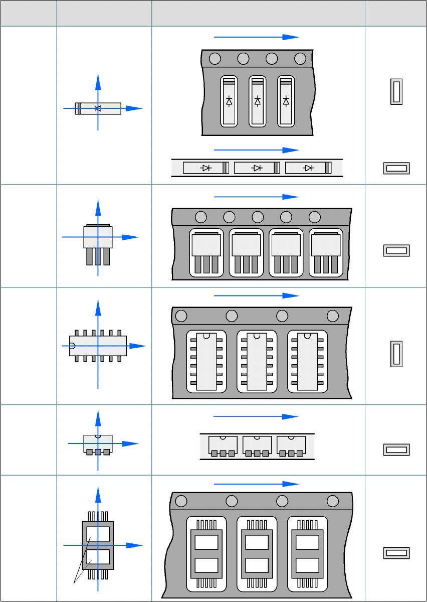
5.8.3 Component coordinate system and pick-up angle
5
Fig. 5.8 - 1 Position of the component and its pick-up angle
Special
component
Stick
magazine:
Chip-
components
with polarity
0402
2220
The anode must be
aligned with the +X
coordinate.
Package form
type
Coordinate system
Position in the feeder module
Pick-up angle/
nozzle angle
Tape:
SOT 23
Stick
magazine:
Tape:
Tape:
SO-IC
DIL-IC
SOT 194
Tape:
Holes
Y
X
Y
X
Y
X
Y
X
Y
X
90°
90°
0°
90°
-90°
0°