X3_X4_Series machine.pdf - 第377页
User manual SIPLAC E X-Series 7 Station extensions Software Vers ion SR.601.xx 11/ 2005 US Ed ition 7.1 Nozzle changer 377 – The Z axis mo ves up again a nd the n ozzle is s tripped from the sl eeve by sp ring w ires. – …

7 Station extensions User manual SIPLACE X-Series
7.1 Nozzle changer Software Version SR.601.xx 11/2005 US Edition
376
WARNING 7
Only install the associated nozzle changer for each placement head. There is a risk of head
crashes with mixed configurations.
7.1.1.6 Description of the functions
The nozzles are seated in nozzle holders and are held in place by a movable locking plate. A
pneumatic cylinder moves the locking plate 7 mm. All the nozzles are either clamped or released,
depending on the position of the locking plate. The default position of the locking plate, i.e. if there
is no nozzle change in progress, is "closed".
Each magazine on the nozzle changer has two positioning fiducials for detecting the position and
orientation of the magazine. The magazine locations are numbered consecutively from 1 - 6 for
the "row 1" nozzle changers and from 7 - 12 for the "row 2" (see Figs. 7.1 - 3
, 7.1 - 2 and 7.1 - 4).
The 12 nozzle garages in the magazines are numbered consecutively (see Fig. 7.1 - 8
).
PLEASE NOTE 7
Special magazines are available upon request (contact SIEMENS A&D for details) and will be
numbered differently.
Picking up a nozzle 7
– The Collect&Place head Z axis moves down.
– The locking plate (item 2 in Fig. 7.1 - 6
) opens and releases the nozzles.
– The nozzle is picked up by the sleeve of the Collect&Place head.
– The Z axis moves up.
Setting down a nozzle 7
– The locking plate (item 2 in Fig. 7.1 - 6) opens and releases the nozzles.
– The Collect&Place head Z axis moves down and sets the nozzle down.
– The locking plate closes.
– The Collect&Place head Z axis moves up.
Discarding defective nozzles 7
– The Collect&Place head Z axis moves down towards the discarding device (item 4 in Figs.
7.1 - 2
, 7.1 - 3 and 7.1 - 4) and thus moves the defective nozzle into the opening in the dis-
carding device. The opening is sized so that the nozzle can no longer be turned. The turning
motion of the DP axis detaches the nozzle from the sleeve.
User manual SIPLACE X-Series 7 Station extensions
Software Version SR.601.xx 11/2005 US Edition 7.1 Nozzle changer
377
– The Z axis moves up again and the nozzle is stripped from the sleeve by spring wires.
– The nozzle drops into the reject bin.
7
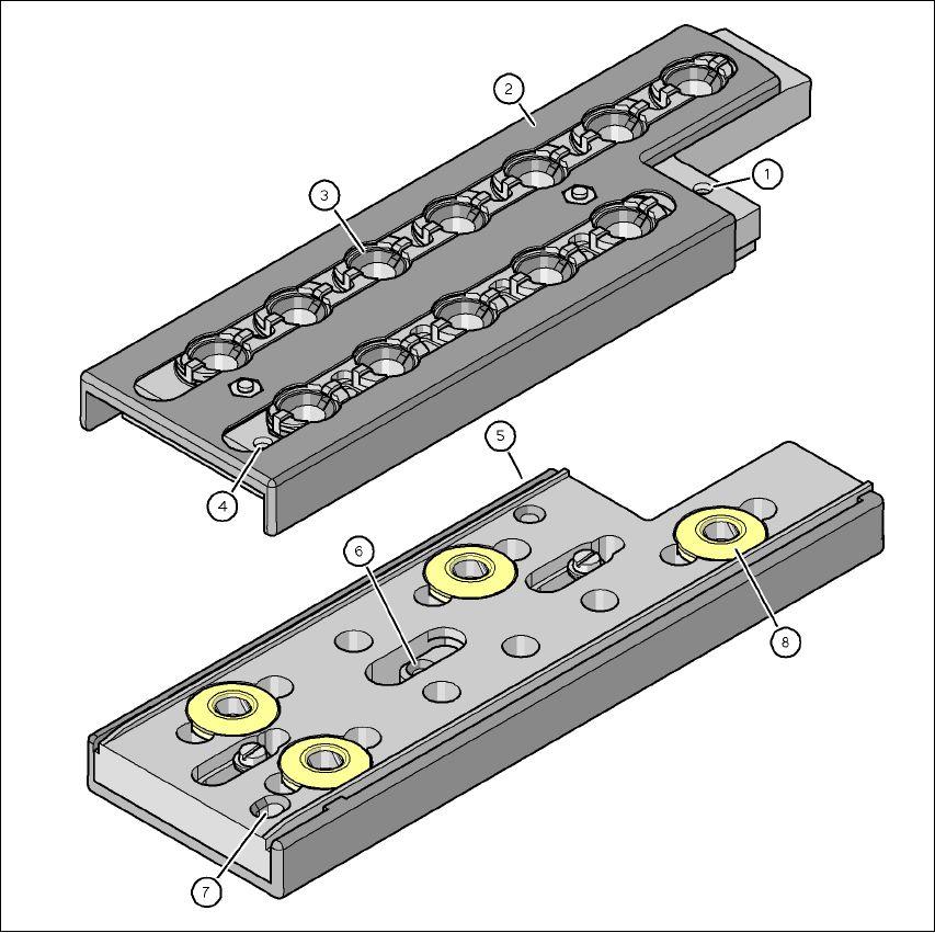
Fig. 7.1 - 6 Magazine and nozzle holders
(1) Fiducial for determining the position
(2) Locking plate in the "Magazine opened" position
(3) Nozzle holder
(4) Fiducial for determining the angular position
(5) Hole for the parallel pin for centering the magazines
(6) Hole for the parallel pin of the slide mechanism
(7) Slot for the parallel pin for centering the magazines
(8) Snap fastening for engaging the magazine into the nozzle changer

7 Station extensions User manual SIPLACE X-Series
7.1 Nozzle changer Software Version SR.601.xx 11/2005 US Edition
378
7.1.1.7 Notes on operation
Æ When you fill a magazine with a certain nozzle type for the first time, attach an adhesive label
to identify the type.
PLEASE NOTE 7
Fill the magazines off the machine and always replace complete magazines. 7
Æ Open the locking plate and place the nozzles in the nozzle holders.
Æ Close the locking plate so that the nozzles cannot drop out of the magazines.
CAUTION 7
Before you fill magazine, make sure that all the nozzles on the Collect&Place head have
been returned to their magazines. 7
PLEASE NOTE 7
Do not allow components to drop onto the magazines. If they do, they could jam the locking
plate. You should therefore regularly clean the magazines and free locations.
Æ Programming the nozzle changer is described in the SIPLACE Pro user manual.
7.1.1.8 Changing the magazine
Æ Press the lever (item 1 in Fig. 7.1 - 7, page 374) to release the magazine from the balls of
the snap fasteners (item 5 in Fig. 7.1 - 7
). Lift the magazine off the base.