X3_X4_Series machine.pdf - 第211页
User manual SIPLAC E X-Series 4 Setting up and commissioning Software Version SR.601.xx 11/2005 US Edition 4.4 Sett ing up the placement machine 211 4.4.8.4 X3 axis uni t (gantry 3) - Connecting the plugs Æ Connect t he …
4 Setting up and commissioning User manual SIPLACE X-Series
4.4 Setting up the placement machine Software Version SR.601.xx 11/2005 US Edition
210
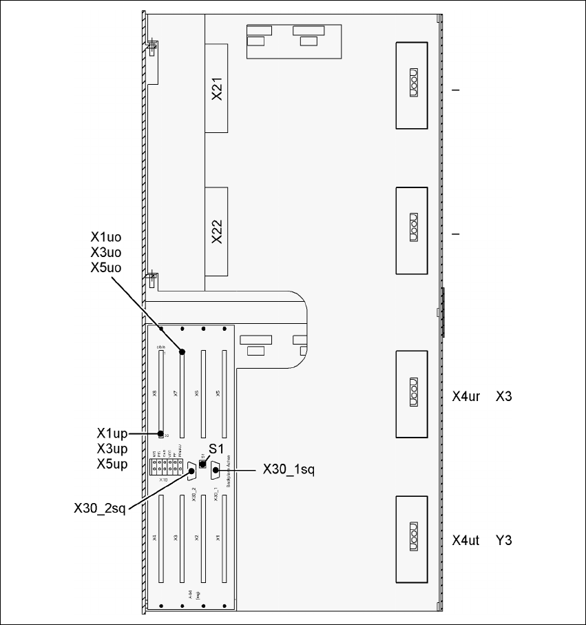
4.4.8.3 X3 axis unit (gantry 3) - Electrical connection points
4
Fig. 4.4 - 13 X3 axis unit (gantry 3), back panel - Electrical connection points

User manual SIPLACE X-Series 4 Setting up and commissioning
Software Version SR.601.xx 11/2005 US Edition 4.4 Setting up the placement machine
211
4.4.8.4 X3 axis unit (gantry 3) - Connecting the plugs
Æ Connect the power cable as shown in the following diagram:
4
4
Æ Check the switch settings for S1
1: ON
2: ON
Æ Continue from section 4.4.8.7 "Fitting the axis unit", page 214.
X3 axis unit (gantry 3)
Plugs
Connecting cable NOTE
Plug Cable
X21 X21
03009782
03009783
03009784
03009785
03009786 W1-W5
Secure connector with clips
X22 X22
03009802
03009803
03009804
03009805
03009807
Secure connector with clips
X4ur X4ur 03009800 Snap connector into place
X4ut X4ut 03009801 Snap connector into place
X1uo
X3uo
X5uo
X1uo
X3uo
X5uo
03009811
03009812
03009813
Insert as far as the stop
X1up
X3up
X5up
X1up
X3up
X5up
03009814
03009815
03009816
Insert as far as the stop
X30_1sq
X30_2sq
X30_1sq
X30_2sq
03010054
03010054
Screw tightly
4 Setting up and commissioning User manual SIPLACE X-Series
4.4 Setting up the placement machine Software Version SR.601.xx 11/2005 US Edition
212
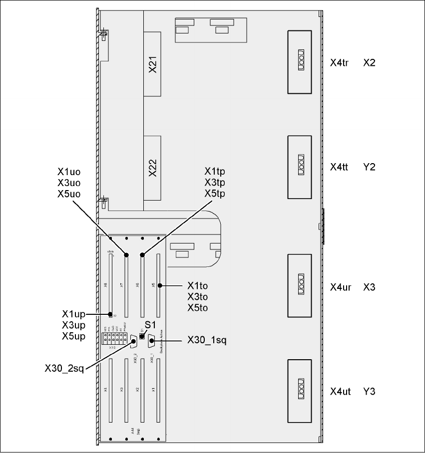
4.4.8.5 X4 axis unit (gantries 2 and 3) - Electrical connection points
4
Fig. 4.4 - 14 X4 axis unit (gantries 2 and 3) - Rear panel - Electrical connection points