X3_X4_Series machine.pdf - 第350页
6 Component handling User manual SIPLACE X-Series 6.7 SIPLACE HF component trolleys Software Version SR.601.xx 11/2005 US E dition 350 6.7 SIPLACE HF comp onent trolleys Up to four SIP LACE HF c omponent tr olleys can be…
User manual SIPLACE X-Series 6 Component handling
Software Version SR.601.xx 11/2005 US Edition 6.6 S feeder modules for the SIPLACE HF component trolley
349
The amount of flux required for the process is reduced to a minimum coating thickness since only
the undersides of the bumps have to be wetted.
The Dip module is suitable for the following placement heads:
6-segment Collect & Place head
12-segment Collect & Place head
TwinHead 6
The Dip module is regarded as a separate feeder module type by the set-up optimization. There
is no limit to the number of dip modules at the individual locations.
6.6.4.2 Technical data
Item no. 00117010-xx 6
Feeder module locations filled 3 6
Component size max. 36 x 36 mm²
depending on the placement head type 6
Possible coating thicknesses 25, 35, 45, 55, 65, 75 µm 6
Time required to change the coating thickness Less than 1 min. 6
Gap height tolerance ± 5 mm 6
Plate rotating speed Programmable from 0 - 10 sec.
in 0.1 sec. increments 6
Component dip time Programmable from 0 - 2 sec.
in 0.1 sec. increments 6
Flux Highly viscous flux, conductive adhesive 6
6
6 Component handling User manual SIPLACE X-Series
6.7 SIPLACE HF component trolleys Software Version SR.601.xx 11/2005 US Edition
350
6.7 SIPLACE HF component trolleys
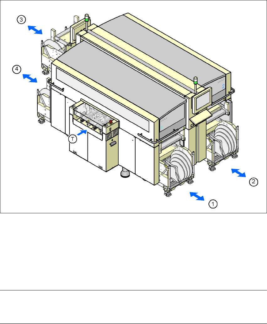
Up to four SIPLACE HF component trolleys can be docked into the machines from the SIPLACE
X-series. The locations are numbered as shown in the diagram below.
6
Fig. 6.7 - 1 Component trolley locations, SIPLACE HF
(1) Location 1
(2) Location 2
(3) Location 3
(4) Location 4
(T) PCB direction of travel
PLEASE NOTE 6
The SIPLACE HF component trolley cannot be used together with the 20-segment Collect &
Place head.
User manual SIPLACE X-Series 6 Component handling
Software Version SR.601.xx 11/2005 US Edition 6.7 SIPLACE HF component trolleys
351
CAUTION 6
The component trolleys from the SIPLACE HF may only be docked into locations at which the
component trolley docking unit for the SIPLACE HF is installed (Fig. 5.10 - 6, page 281).
The component changeover tables are stand-alone modules that can be set up with feeders at an
external set-up area. This means that the production process only has to be interrupted briefly in
order to change the component trolley.
PLEASE NOTE:
At external set-up positions, you will need an external power supply for the component trolley
(see section 6.7.5, page 357).
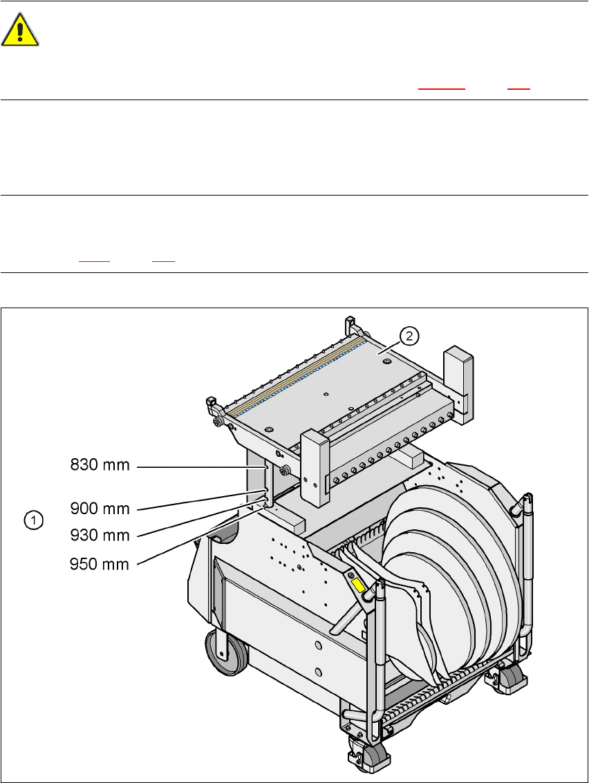
Fig. 6.7 - 2 SIPLACE HF component trolley with a PCB conveyor height of 950 mm
6
(1) Holes in the guide columns for the transport heights of 830 to 950 mm
(2) Component trolley table