X3_X4_Series machine.pdf - 第398页
7 Station extensions User manual SIPLACE X-S eries 7.1 Nozzle changer Software Version S R.601.xx 11/2005 US Edition 398 7.1.3.6 Des cription of the funct ions The nozz les are s eated in n ozzle h olders and are he ld i…
User manual SIPLACE X-Series 7 Station extensions
Software Version SR.601.xx 11/2005 US Edition 7.1 Nozzle changer
397
7.1.3.4 Technical data
7
7.1.3.5 Assembly
The "Row 1" nozzle changer (see Figs. 7.1 - 22, 7.1 - 21 and 7.1 - 20) is fixed to the component
trolley docking unit. There is an additional assembly kit for the "row 2" nozzle changer. This kit
consists of the take-off device and the nozzle reject bin (see section 7.1.3.10
).
7
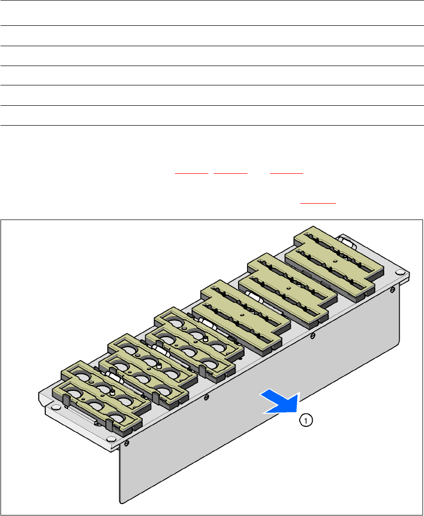
Fig. 7.1 - 23 Assembly position
(1) Cover plate pointing toward the PCB conveyor
7
Æ Align the nozzle changer so that the cover plate (item 1) points toward the PCB conveyor.
Nozzle changer for the 6-segment Collect&Place head
Dimensions (length x width x height) 448 x 122.5 x 97.7 mm³
Number of nozzle holders 6
Nozzle types 8 xx, 9 xx
Time required to open and close the locking plate < 200 ms
Compressed air connection 0.48 MPa (4.8 bar)

7 Station extensions User manual SIPLACE X-Series
7.1 Nozzle changer Software Version SR.601.xx 11/2005 US Edition
398
7.1.3.6 Description of the functions
The nozzles are seated in nozzle holders and are held in place by a movable locking plate.
A pneumatic cylinder moves the locking plate 12 mm. All the nozzles are either clamped or re-
leased, depending on the position of the locking plate. The default position of the locking plate,
i.e. if there is no nozzle change in progress, is "closed".
Every magazine of the nozzle changer has a positioning fiducial for position detection. The mag-
azine locations are numbered consecutively from 1 - 6 for the "row 1" nozzle changers and from
7 - 12 for the "row 2" (see Figs. 7.1 - 22
, 7.1 - 21 and 7.1 - 20). The 6 nozzle holders in the mag-
azines are also numbered consecutively (see Fig. 7.1 - 24
).
PLEASE NOTE 7
Special magazines are available upon request (contact SIEMENS A&D for details) and will be
numbered differently.
Picking up a nozzle 7
– The Collect&Place head Z axis moves down.
– The locking plate (item 2 in Fig. 7.1 - 24
, page 399) opens and releases the nozzles.
– The nozzle is picked up by the sleeve of the Collect&Place head.
– The Z axis moves up.
Setting down a nozzle 7
– The locking plate (item 2 in Fig. 7.1 - 24, page 399) opens and releases the nozzles.
– The Collect&Place head Z axis moves down and sets the nozzle down.
– The locking plate closes.
– The Collect&Place head Z axis moves up.
Discarding defective nozzles 7
– The Collect&Place head Z axis moves down 14 mm towards the discarding device (item 4 in
Fig. 7.1 - 22
, 7.1 - 21 and 7.1 - 20) and thus moves the defective nozzle into the hole in the
discarding device.
– The Z axis moves up again and the nozzle is stripped from the sleeve by spring wires.
– The nozzle drops into the reject bin.
User manual SIPLACE X-Series 7 Station extensions
Software Version SR.601.xx 11/2005 US Edition 7.1 Nozzle changer
399
7
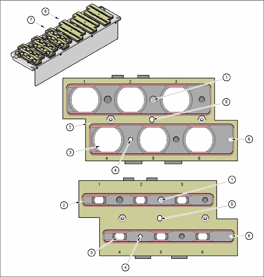
Fig. 7.1 - 24 Magazine and nozzle holders
(1) Positioning fiducial
(2) Locking plate
(3) Nozzle holder for type 9xx and 8xx nozzles
(4) Hole for the parallel pin for centering the magazines
(5) Hole for the parallel pin of the slide mechanism
(6) Slot for the parallel pin for centering the magazines
(7) Magazine for type 8xx nozzles
(8) Magazine for type 9xx nozzles