X3_X4_Series machine.pdf - 第319页
User manual SIPLAC E X-Series 6 Component han dling Software Version SR.601.xx 11/2005 US Edition 6.5 Docking station for the component trolley from the SIPLACE X-series 319 6.5 Docking st ation for the comp onent troll …
6 Component handling User manual SIPLACE X-Series
6.4 Used tape channel - CO trolley docking unit, SIPLACE X-series Software Version SR.601.xx 11/2005 US Edition
318
6.4.2 Removing the separating plate for tape pocket heights > 12 mm
If X feeder modules are used, the component tapes work with a pocket height > 12 mm, so the
separating plate (item 3 in Fig. 6.4 - 1
) must be removed.
WARNING 6
Æ Switch the placement machine off at the main switch to remove the dividing plate.
Æ Disconnect the machine from the power and compressed air supply.
Æ Secure the machine to prevent it being switched on again, as described in section 2.10, page
86
.
Æ Wait until the operating pressure for the tape cutter has dropped to 0 MPa.
Æ Do not reach inside the used tape channel.
Æ Loosen the two hexagon head screws (item 4 in Fig. 6.4 - 1).
Æ Pull out the dividing plate.
PLEASE NOTE
Do not position feeder modules with shallow pockets immediately beside bar feeder modules
with deep pockets. The used tapes could overlap and build up.
6
User manual SIPLACE X-Series 6 Component handling
Software Version SR.601.xx 11/2005 US Edition 6.5 Docking station for the component trolley from the SIPLACE X-series
319
6.5 Docking station for the component trolley from the
SIPLACE X-series
Item no. 00116933-xx
6.5.1 Overview
The docking station is an additional component the set-up area. It forms the link between the set-
up area and the component trolley for the SIPLACE X-series. The docking station allows the com-
ponent trolleys to be set up with feeder modules and function tests and set-up checks to be carried
out externally.
6
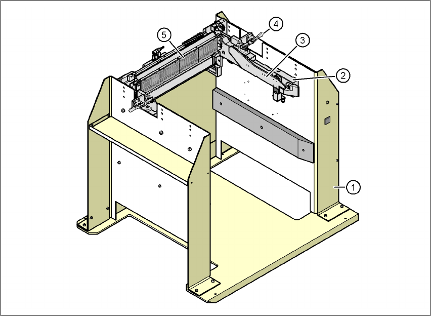
Fig. 6.5 - 1 Docking station, SIPLACE X-series
(1) Docking station
(2) Component trolley docking unit, X-series
(3) Rails for guiding and docking in the component table
(4) Horizontal tensioner for locking the component trolley
(5) EDIF (energy and data interface)
6 Component handling User manual SIPLACE X-Series
6.5 Docking station for the component trolley from the SIPLACE X-series Software Version SR.601.xx 11/2005 US Edition
320
The basic tasks of the docking station are as follows:
– Supplying the component trolley and X feeder modules with power
– Supplying the component trolley and X feeder modules with compressed air
– Providing an infrastructure for communication between the PC at the set-up area and the
feeder modules
6.5.2 Description of the functions
The operator can use the docking station to carry out function tests on the X feeder modules and
check the set-up outside the production environment. Two rows, each with four docking stations,
are connected via the CAN bus of the initial set-up PC. Each docking station has a separate power
and compressed air connection.
The component trolley docking unit (item 2 in Fig. 6.5 - 1
) of the docking station can be adapted
to the desired PCB conveyor height. For the initial set-up, the component trolley is pushed into the
docking station (item 1 in Fig. 6.5 - 1
). The component trolley slides on the rails of the component
trolley docking unit, using the roller bearings attached to the sides of the component trolley, to the
energy and data interface connection. The component table is positioned with the EDIF of the
feeder modules optimally with respect to the EDIF (item 4 in Fig. 6.5 - 1
) of the component trolley
docking station, and is fixed in this position with the two horizontal tensioners.
6.5.3 Technical data
6
Dimensions
Length x width 950 mm x 930 mm
Height 794 mm for 830 mm PCB transport height
864 mm for 900 mm PCB transport height
894 mm for 930 mm PCB transport height
914 mm for 950 mm PCB transport height
Weight 120 kg
Compressed air pressure
p
min
p
max
0.5 MPa (5.0 bar)
1.0 MPa (10.0 bar)
Compressed air connection Coupler plug KS 2-M5-A
Compressed air consumption 50 l/min.
Supply voltage 88 - 264 VAC
Rated current 3.5 A (230 VAC)
7 A (115 VAC)
Nominal apparent power 0.8 kW
Fuses 2 x 8 A