X3_X4_Series machine.pdf - 第246页
4 Setting up and commissioning User manual SIPLACE X-Series 4.7 Adapting the SI PLACE HF c omponent trolley to the PCB transport height Software Version S R.601.xx 11/2005 US Edition 246
User manual SIPLACE X-Series 4 Setting up and commissioning
Software Version SR.601.xx 11/2005 US Edition 4.7 Adapting the SIPLACE HF component trolley to the PCB transport height
245
4
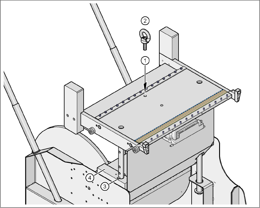
Fig. 4.7 - 2 Positions of the eye-bolt on the SIPLACE HF component trolley
(1) M12 hole for eye-bolt
(2) Eye-bolt, DIN 580 M12-St
(3) Spiral clamping pin, DIN 7343, 8x40 - St, 2x
(4) Supporting block, 2x
4 Setting up and commissioning User manual SIPLACE X-Series
4.7 Adapting the SIPLACE HF component trolley to the PCB transport height Software Version SR.601.xx 11/2005 US Edition
246

User manual SIPLACE X-Series 5 Tasks on the machine
Software Version SR.601.xx 11/2005 US Edition 5.1 Personnel profile
247
5 Tasks on the machine
This chapter contains a number of subjects that are intended to help you during your daily work
on a SIPLACE line.
For example, you are provided with preventative measures that you can take to minimize the down
time on the machine to obtain the highest possible level of efficiency for the SIPLACE line during
production.
In addition, the tasks of the operator and of the line engineer are described in an operator and line
engineer profile, respectively, in this chapter.
5.1 Personnel profile
5.1.1 Operator
5.1.1.1 Tasks of the operator
The operators should generally have attended the SIPLACE operation training course or have
been instructed by trained personnel.
The operating personnel are to be assigned the following tasks:
– Checking the assignment of components to the feeder modules
Æ To do this, a set-up check is to be carried out several times a day, preferably at the start
of a shift, to make sure that the correct components are set up.
– Supplying the feeder modules with sufficient components
– Promptly refilling the components and splicing the tapes
– Emptying the cover foil container (after every splicing operation, for example)
– Checking to make sure that the components are in their correct pick-up positions (see Fig.
5.8 - 1
)
– Checking the flow of material to the PCBs on the input and output conveyor
– Checking the set-up quality
– Random sampling of the PCBs before they enter the soldering furnace.
– Observing the ESD regulations
– Observing the fault displays and messages at the station and passing the information on to
the line engineer if necessary
– Carrying out the preventive maintenance work specified in the Preventive Maintenance
Manual