X3_X4_Series machine.pdf - 第148页
3 Technical data User manual SIPLACE X-Series 3.10 Gantries Software Version S R.601.xx 11/2005 US Edition 148 3.10 Gantries 3.10.1 Position of the gantries for th e X4 placement machine 3 Fig. 3.10 - 1 Position of the g…
User manual SIPLACE X-Series 3 Technical data
Software Version SR.601.xx 11/2005 US Edition 3.9 Controls
147
3.9.3.1 Controls on the placement machine's operator panels
The two operator panel have identical control functions.
Monitor, keyboard, Start and Stop buttons 3
There is a monitor and a keyboard on both sides of the placement machine.
The Start and Stop buttons are located beneath the keyboard. The on-screen dialog will occasion-
ally prompt you to activate certain actions using buttons, and this arrangement will make it easier
for you both to activate and to interactively control these actions.
Main power switch 3
The main power switch is part of the power module. It is located on the left-hand operator panel
viewed in the direction of PCB transport. It is located here because it is only needed for servicing
and preventive maintenance work and is therefore not subject to frequent use.
3.9.3.2 Controls on the input and output sides of the placement machine
The controls on the input and output sides of the placement machine perform identical functions.
Emergency stop buttons, Start and Stop buttons 3
There is an emergency stop button and Start and Stop buttons on both the input and output sides
of the PCB conveyor. This arrangement was adopted for the buttons because it enables them to
be reached quickly and easily from any position.
In addition, it is important to have an unrestricted view of the placement heads and placement area
during preventive maintenance, servicing and setting up work in order to be able to check all the
operations carried out inside the machine. This particularly important during testing phases or
when starting single functions, for example.
3 Technical data User manual SIPLACE X-Series
3.10 Gantries Software Version SR.601.xx 11/2005 US Edition
148
3.10 Gantries
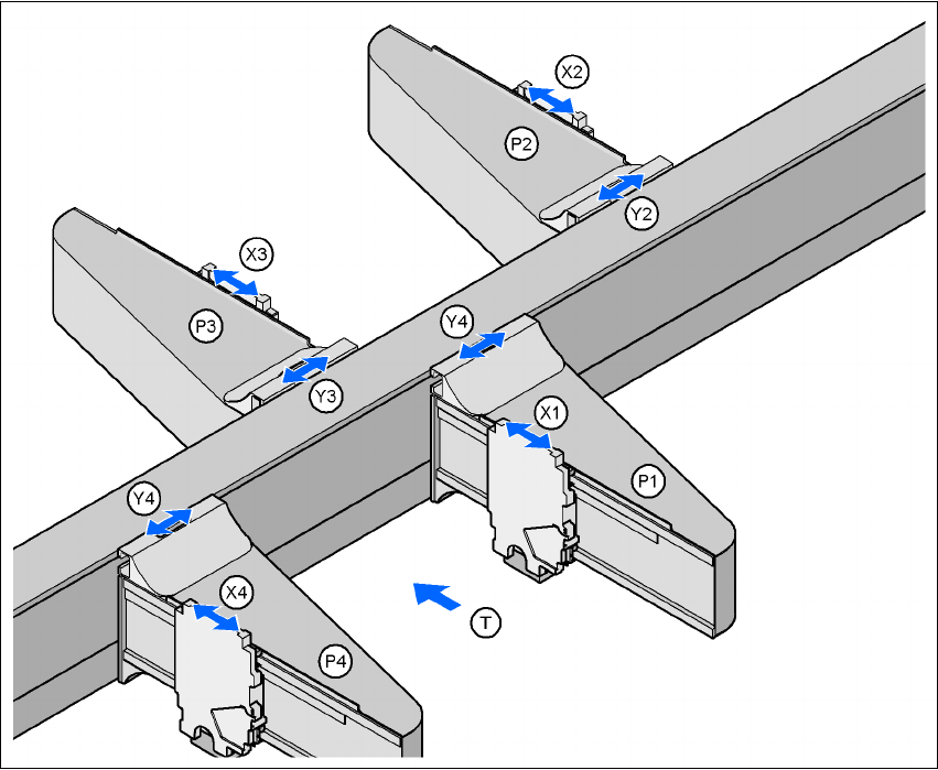
3.10.1 Position of the gantries for the X4 placement machine
3
Fig. 3.10 - 1 Position of the gantries for the X4 placement machine
G1, G2, G3, G4 (gantry 1, gantry 2, gantry 3, gantry 4)
X1 X axis, gantry 1
Y1 Y axis, gantry 1
X2 X axis, gantry 2
Y2 Y axis, gantry 2
X3 X axis, gantry 3
Y3 Y axis, gantry 3
X4 X axis, gantry 4
Y4 Y axis, gantry 4
(T) Direction of PCB transport
Placement area 2
Placement area 1
User manual SIPLACE X-Series 3 Technical data
Software Version SR.601.xx 11/2005 US Edition 3.10 Gantries
149
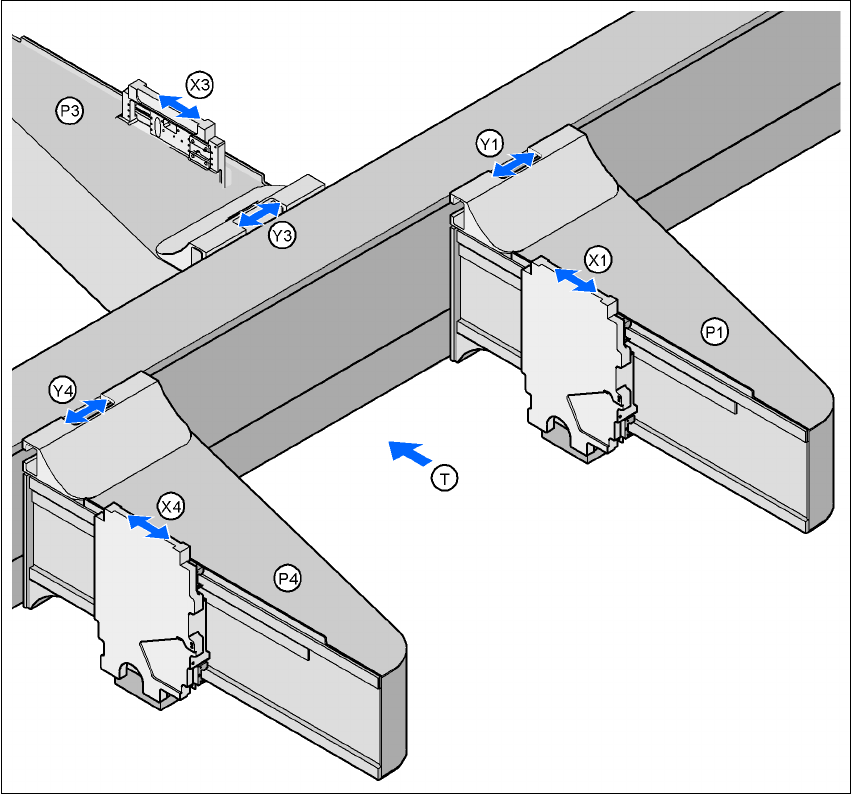
3.10.2 Position of the gantries for the X3 placement machine
3
Fig. 3.10 - 2 Position of the gantries for the X3 placement machine
G1 Gantry 1
X1 X axis, gantry 1
Y1 Y axis, gantry 1
P3 Gantry 3
X3 X axis, gantry 3
Y3 Y axis, gantry 3
P4 Gantry 4
X4 X axis, gantry 4
Y4 Y axis, gantry 4
(T) Direction of PCB transport
Placement area 2
Placement area 1