X3_X4_Series machine.pdf - 第284页
5 Tasks on the machine User manual SIPLAC E X-Series 5.11 Note operating status indicator lamp Software Version SR.601.xx 11/2005 US E dition 284 – Left white fault i ndicator l amp L3 fla shes One or m ore tracks ar e e…
User manual SIPLACE X-Series 5 Tasks on the machine
Software Version SR.601.xx 11/2005 US Edition 5.11 Note operating status indicator lamp
283
5.11 Note operating status indicator lamp
The indicator lamp is used to signal operating statuses and malfunctions of the placement system.
5.11.1 Description of the functions
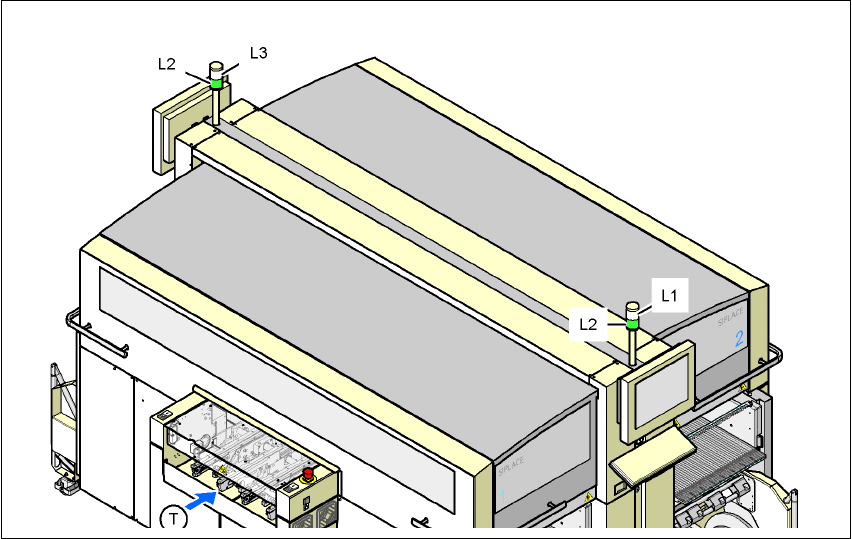
Fig. 5.11 - 1 Operating status indicator lamp
L1 Fault indicator lamp (white, right)
L2 Operating status indicator lamp (green, both lamps switched in parallel)
L3 Fault indicator lamp (white, left)
T Direction of PCB transport
5.11.2General operating statuses
–
Operating status indicator lamp (green) on continuously
The placement system is in service.
–
Operating status indicator lamp (green) flashes
The placement system is waiting for a PCB on the input belt or the placement system is wait-
ing until the output belt is free.
–
Right white fault indicator lamp L1 flashes
One or more tracks are empty on the right-hand side of the placement system. The placement
system continues to place any remaining components.

5 Tasks on the machine User manual SIPLACE X-Series
5.11 Note operating status indicator lamp Software Version SR.601.xx 11/2005 US Edition
284
–
Left white fault indicator lamp L3 flashes
One or more tracks are empty on the left-hand side of the placement system. The placement
system continues to place any remaining components.
–
Right white fault indicator lamp (L1) on continuously - green operating status lamp (L2) off
An error has occurred on the right-hand side of the placement system -> the placement sys-
tem has stopped.
–
Left white fault indicator lamp (L1) on continuously - green operating status lamp (L2) off
An error has occurred on the left-hand side of the placement system -> the placement system
has stopped.
–
Both white fault indicator lamps (L1 and L3) on continuously - green operating status lamp off
An error has occurred that affects the entire placement system -> the placement system has
stopped.
5.11.3 Programmed operating status displays
The following table shows the programmed operating status displays in the standard configuration
(version as supplied) and lists their meaning on the individual lamps of the main fault indicator.
The entries in the table next to "flashes" refer to the frequency with which the relevant lamp flashes
for a given event. The entry (1, 5), for example, can be explained as follows:
– The first number in the brackets indicates the time, expressed in 100 msec intervals, for which
the fault indicator lamp is switched on, i.e. 1 x 100 msec in the above example.
– The second number in the brackets indicates the time, expressed in 100 msec intervals, for
which the fault indicator lamp is switched off, i.e. 5 x 100 msec in the above example.
5
L1 (white)
(right lamp)
L2 (green) L3 (white)
(left lamp)
Meaning
Status display
flashes (1,10) flashes (7,7) flashes (1,10) Reference run
unchanged flashes (1,5) unchanged Waiting until axes in position
unchanged flashes (7,7) unchanged Waiting for setup data
unchanged flashes (7,7) unchanged Waiting for cluster data
unchanged flashes (7,7) unchanged Load table program
unchanged flashes (7,7) unchanged Position detection
unchanged flashes (1,10) unchanged Bad fiducial detection
unchanged flashes (7,7) unchanged Nozzle configuration test
unchanged flashes (7,7) unchanged Feeder position detection
unchanged flashes (7,7) unchanged One track is empty
unchanged flashes (7,7) unchanged No further track available

User manual SIPLACE X-Series 5 Tasks on the machine
Software Version SR.601.xx 11/2005 US Edition 5.11 Note operating status indicator lamp
285
unchanged flashes (7,7) unchanged Go to refill position
unchanged flashes (7,7) unchanged Transport being initialized
unchanged flashes (7,7) unchanged Place PCB in input conveyor
flashes (1,10) flashes (7,7) unchanged Remove PCB from output conveyor
unchanged flashes (7,7) flashes (1,10) Remove PCB from output conveyor 2
flashes (1,10) flashes (7,7) flashes (1,10) Width adjustment
unchanged flashes (1,10) unchanged Transport PCB
flashes (1,10) flashes (7,7) flashes (1,10) Both output conveyors are cleared
on flashes (1,10) on Transport error
on off on Go to service position
on Placement
flashes (1,20) Waiting for processing data
Error display
on off unchanged Machine error, right
on off unchanged Track empty, right
on off unchanged Nozzle configuration, right
on off unchanged Transport error, right
on off on Fiducial error, left and right
on off on Fiducial error, left and right
unchanged off on Track empty, left
unchanged off on Nozzle configuration, left
unchanged off on Transport error, left
unchanged off on Machine error, left
Pick-up error display
unchanged unchanged flashes (1,20)
First track empty, left
unchanged unchanged flashes (5,20)
Further tracks empty, left
unchanged unchanged flashes (5,5)
Penultimate track in use
unchanged unchanged flashes (1,2)
Last track in use, right
flashes (1,20) unchanged unchanged
First track empty, right
flashes (5,20) unchanged unchanged
Further tracks empty, right
flashes (5,5) unchanged unchanged
Penultimate track in use, right
flashes (1,2) unchanged unchanged
Last track in use, right
L1 (white)
(right lamp)
L2 (green) L3 (white)
(left lamp)
Meaning