X3_X4_Series machine.pdf - 第78页
2 Operational safety User manual SIPLACE X-Series 2.8 Disabling the compressed air supply and discharging the pressure Software Version SR.601.xx 11/2005 US Edition 78 Fig. 2.8 - 1 Compress ed air unit on t he placement …
User manual SIPLACE X-Series 2 Operational safety
Software Version SR.601.xx 11/2005 US Edition 2.8 Disabling the compressed air supply and discharging the pressure
77
2.7.2 Residual voltages and discharge times after switching off at the main switch
2
CAUTION 2
To avoid losing data, assess the following criteria before switching off your automatic placement
system (apart from in emergencies):
– Has the placement system finished transmitting machine, setup and panel data?
– Has the placement system finished processing the PCB?
– Has the placement system completed the run-up phase?
2.8 Disabling the compressed air supply and discharg-
ing the pressure
The compressed air working pressure of the placement system is set to 0.50 ± 0.025 MPa (5.0 ±
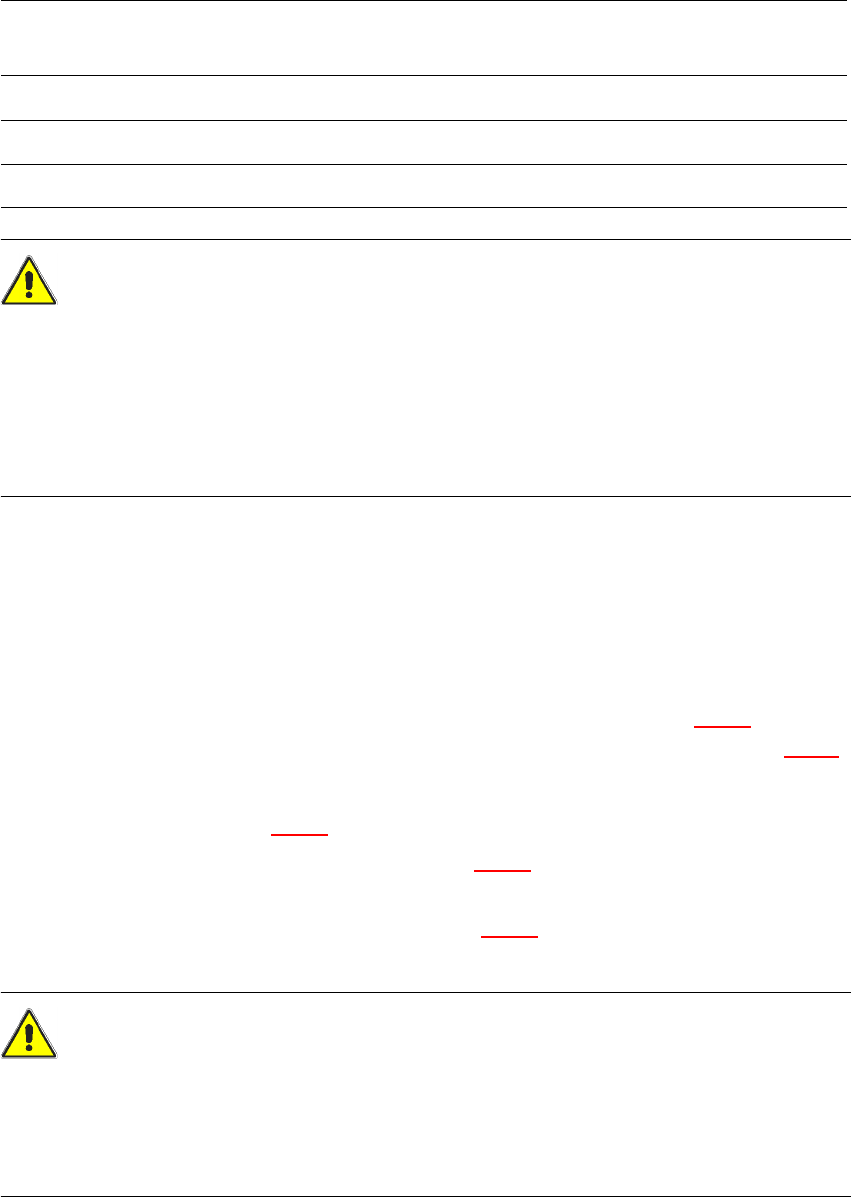
0.25 bar). The position of the compressed air unit is indicated by item 1 in Fig. 2.8 - 1
. The com-
pressed air supply to the machine can be interrupted using the shutoff valve (item 2 in Fig. 2.8 - 1
).
Æ Use the machine key to release the cover lock.
Æ Lift off the cover (see Fig. 2.8 - 1).
Æ Turn the lever on the shutoff valve (item 1 in Fig. 2.8 - 1) from the vertical to the horizontal
position.
Æ Watch the working pressure gauge (item 5 in Fig. 2.8 - 1). When the automatic placement
system is switched on, the pressure discharges to 0 MPa (0 bar) within 1 minute.
CAUTION
When the machine is switched on, do not use the stop valve to interrupt the compressed air sup-
ply for more than 30 minutes. If you need to shut off the pneumatic system for longer in order to
carry out preventive maintenance or servicing work, you must switch the placement system off at
the main switch and disconnect it from the power supply.
Pins X11, X13_1 and X13_4
measured to X12 (GND)
Residual voltages when
main power switch is off Discharge times
X11 < 10 VDC < 7 sec
X13_1 < 10 VDC < 50 sec
X13_4 < 10 VDC < 2 sec
2 Operational safety User manual SIPLACE X-Series
2.8 Disabling the compressed air supply and discharging the pressure Software Version SR.601.xx 11/2005 US Edition
78
Fig. 2.8 - 1 Compressed air unit on the placement system
(1) Stop valve
(2) Manometer for the machine component supply pressure
Desired pressure: 0.48 ± 0.025 MPa, 4.8 ± 0.25 bar (display range 0 - 0.6 MPa, 0 - 6 bar)
(3) Manometer for the gantry distributor supply pressure
Desired pressure: 0.46 ± 0.01 MPa, 4.6 ± 0.1 bar (display range 0 - 0.6 MPa, 0 - 6 bar)
(4) Manometer for the bulk case feeder modules supply pressure
Desired pressure: 0.25 ± 0.05 MPa, 2.5 ± 0.5 bar (display range 0 - 0.6 MPa, 0 - 6 bar)
(5) Manometer for the input pressure
Desired pressure: 0.5 - 1.0 MPa, 5 - 10 bar (display range: 0 - 1.0 MPa, 0 - 10 bar)
(6) Compressed air filter
(7) Hexagon socket head screw for fixing the pneumatic board
WARNING
NEVER detach compressed air lines while they are still pressurized. Risk of injury. 2
User manual SIPLACE X-Series 2 Operational safety
Software Version SR.601.xx 11/2005 US Edition 2.9 Energy state of the machine after switching off at the main power switch
79
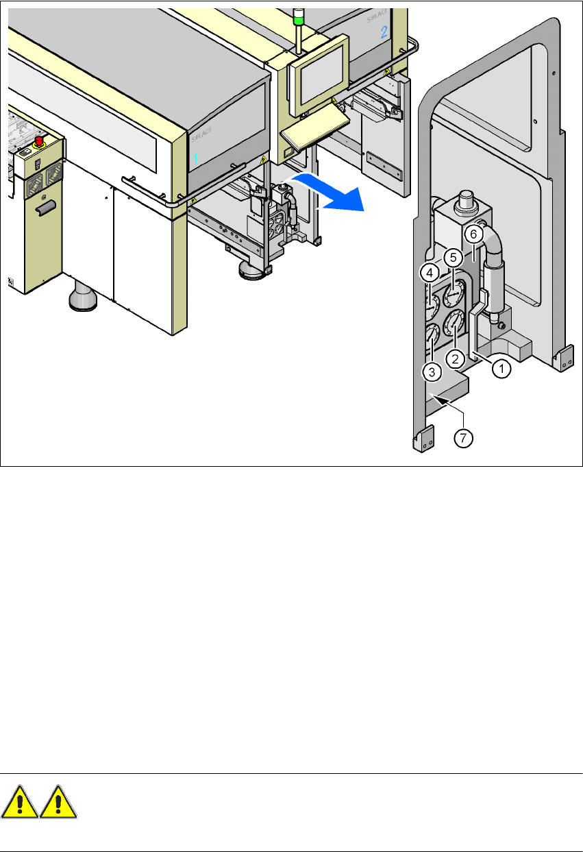
2.9 Energy state of the machine after switching off at
the main power switch
2
Fig. 2.9 - 1 Position of the power supply on the machine
2
WARNING
The placement system is supplied with 3 x 208 VAC, 3 x 230 VAC, 3 x 380 VAC, 3 x 400 VAC or
3 x 415 VAC ± 5 %, 50/60 Hz mains voltage. This means that some parts of the system carry po-
tentially lethal voltages - even when switched off at the main power switch. Incorrect handling of
the placement system can therefore result in death or severe injury or considerable damage to
equipment. 2
Æ Always follow the applicable accident prevention and DIN regulations (particularly DIN EN 60
204, part 1).
Æ The guard over the power supply unit must ONLY be opened by appropriately qualified and
trained personnel.
(1) Main power switch