X3_X4_Series machine.pdf - 第416页
7 Station extensions User manual SIPLACE X-S eries 7.4 Multicolor PCB camera, type 24, digital Software V ersion SR.601.xx 11/2005 US Edition 416 7.4.3 T ype of illumination The foll owing type s of illumi nation can be …
User manual SIPLACE X-Series 7 Station extensions
Software Version SR.601.xx 11/2005 US Edition 7.4 Multicolor PCB camera, type 24, digital
415
7.4 Multicolor PCB camera, type 24, digital
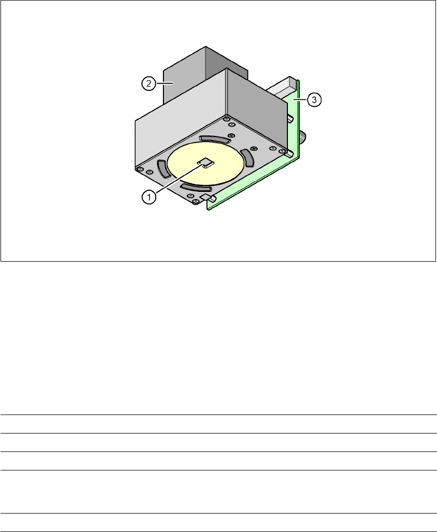
7.4.1 Structure
Item no. 00119774-xx
7
Fig. 7.4 - 1 Digital multicolor PCB camera, type 24
(1) PCB camera lens and illumination
(2) Camera amplifier
(3) Illumination control
7
7
7.4.2 Technical data
7
Field of vision 5.7 x 5.7 mm²
Distance from the focus plane 28 mm
Method of illumination Front-lighting (5 levels, programable as required)
Fiducial size 0.3 mm to 2.5 mm edge length for a PCB feeder tolerance
of ± 1.0 mm
to 3.0 mm edge length for a PCB feeder tolerance of < 1.0 mm
Bad fiducial size 0.3 mm to 3.0 mm edge length

7 Station extensions User manual SIPLACE X-Series
7.4 Multicolor PCB camera, type 24, digital Software Version SR.601.xx 11/2005 US Edition
416
7.4.3 Type of illumination
The following types of illumination can be selected on the multicolor PCB camera:
– White lighting
This type of illumination is used for standard PCBs with tinned fiducials.
– Blue oblique lighting
In most cases, this can be used to greatly improve the contrast with bright fiducials on a light
base material, such as ceramic or CEM. Fiducials covered with solder resist can also be de-
tected better on a light background.
– Infrared lighting
This type of illumination is particularly useful for fiducials that are covered with solder resist
or for fiducials on flex materials. It is also sometimes possible to improve detection of silver/
platinum fiducials on ceramic. This should be tested by carrying out a test centering or place-
ment run.
7.4.4 Fiducial and ink spot criteria
The fiducials and ink spot criteria are described in sections 3.11.5.3 and 3.11.5.4, page 162.

User manual SIPLACE X-Series 7 Station extensions
Software Version SR.601.xx 11/2005 US Edition 7.5 PCB barcode scanner
417
7.5 PCB barcode scanner
Item no. 00119682-xx 1D PCB barcode scanner
Item no. 00119679-xx 2D PCB barcode scanner
Item no. 00119684-xx PCB barcode scanner assembly kit
7.5.1 Overview
The PCB barcode scanner is used to automatically record and decode barcodes on PCBs. The
PCB barcode scanner sends the read data via its serial interface to the transport controller and
then for further processing to the machine controller via the CAN bus.
Fig. 7.5 - 1 PCB barcode block diagram
7
The PCB barcode scanners are installed on the input side of the placement machine on the PCB
conveyor. Up to four devices can be retrofitted to each machine. The barcode scanners are fitted
so that the barcode labels on the topside and underside of the PCBs can be scanned on both
tracks of the dual conveyor.
There are two variants of the barcode scanner:
– 1D barcode scanner
This barcode scanner processes barcodes. 7
– 2D barcode scanner
Device number
1
Barcode
scanner
topside
Distribution
board
Transport
controller,
right
Barcode
scanner
underside
2
3
Barcode
scanner
topside
Distribution
board
Transport
controller,
left
Barcode
scanner
underside
4
Machine
controller
Station
computer
SIPLACE Pro
computer
LAN
CAN
bus
V-24V-24