X3_X4_Series machine.pdf - 第255页
User manual SIPLAC E X-Series 5 Tasks on the machine Software Vers ion SR.601.xx 11/ 2005 US Ed ition 5.3 Carrying out a walk-through inspe ction 255 5.3.6 Inserting sep arating plat es in the ta pe container Æ The separ…
5 Tasks on the machine User manual SIPLACE X-Series
5.3 Carrying out a walk-through inspection Software Version SR.601.xx 11/2005 US Edition
254
5.3.5 Support for an additional tape reel (X-series)
5
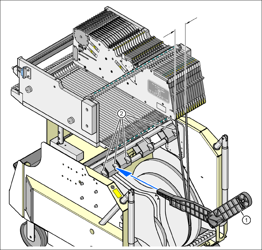
Fig. 5.3 - 3 Support for an additional tape reel (X-series)
(1) Support for an additional tape reel, item no. 00141217-xx
(2) Mounting device for the support
5
X-series feeder modules can process component tapes without problems if the lateral offset be-
tween the feeder module and the tape reel does not exceed 60 mm. If a predefined set-up means
that the maximum permitted offset cannot be maintained, we recommend that you use the mount
for an additional tape reel (item 1). Simply insert the mount into the holder (item 2) and push it until
the offset is less than the maximum permitted value of 60 mm. The component trolley has 5 hold-
ers in total. Each tape reel mount can hold 2 tape reels, which means that up to ten 15" (381 mm)
reels can be positioned above the tape container.
max. 60 mm
User manual SIPLACE X-Series 5 Tasks on the machine
Software Version SR.601.xx 11/2005 US Edition 5.3 Carrying out a walk-through inspection
255
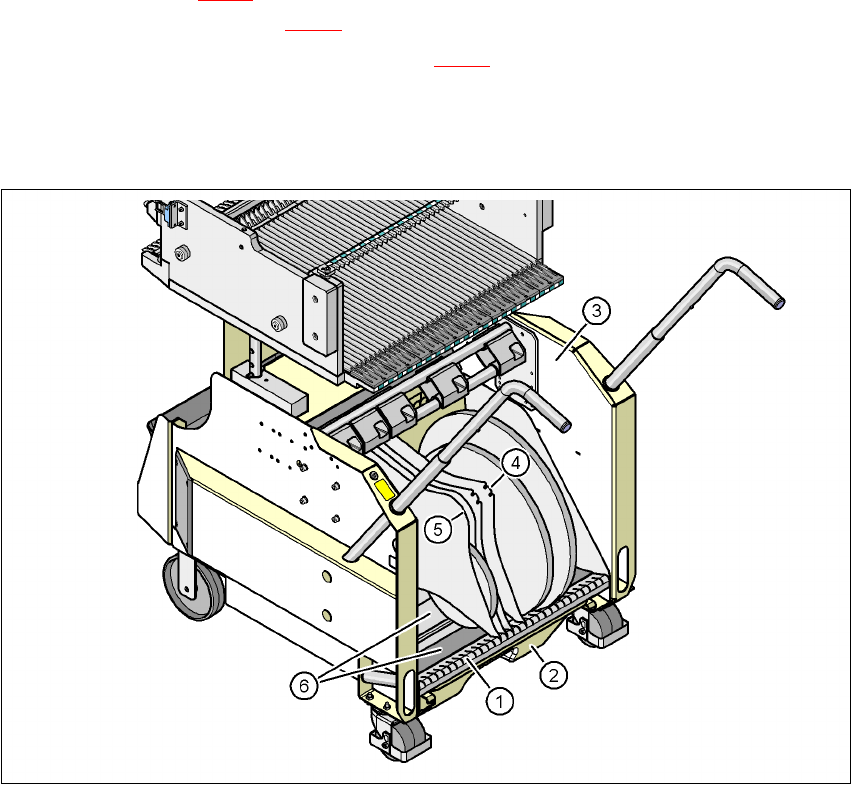
5.3.6 Inserting separating plates in the tape container
Æ The separating plate has different edges and can be inserted into the tape container in two
ways. If spindles are used, the recesses for the spindles in the separating plate point upwards
(see item 4 in Fig. 5.3 - 4
). If you do not use spindles, the
rounded
edge of the separating plate
points up (see item 5 in Fig. 5.3 - 4
).
Æ Insert the separating plates as shown in Fig. 5.3 - 4 and remember that the smallest division
of the tape container is a 2x division. This will help avoid placement errors.
Æ Check that the separating plates engage in the same positions on the three guide rails. Oth-
erwise the separating plate will be offset or bent.
5
Fig. 5.3 - 4 Separating plates in the tape container
(1) Guide rail for the separating plates
(2) Waste tape container
(3) Tape container
(4) Position of the separating plate if spindles are used
(5) Position of the separating plate if no spindles are used
(6) Sliding surfaces for the tape reels
5 Tasks on the machine User manual SIPLACE X-Series
5.3 Carrying out a walk-through inspection Software Version SR.601.xx 11/2005 US Edition
256
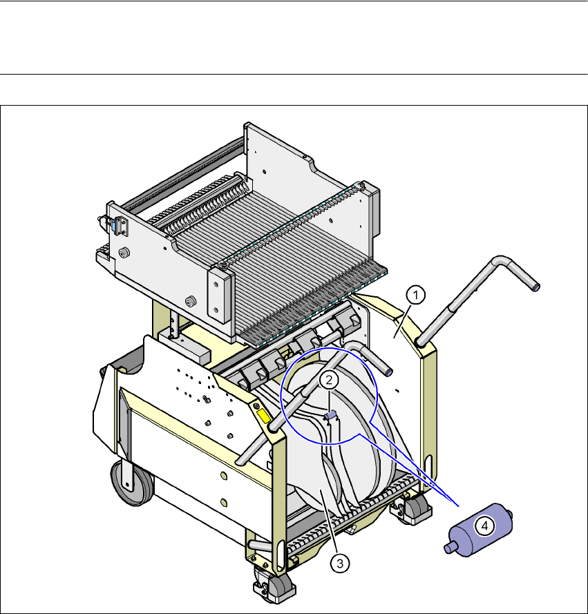
5.3.7 Using spindles for large tape reels
Æ Insert spindles into the separating plates when using large tape reels.
PLEASE NOTE 5
We recommend that you use spindles if the tape reel diameter exceeds 15" (381 mm)". This will
ensure that the feeder modules operate reliably.
Fig. 5.3 - 5 Inserting spindles for large reels
5
(1) Tape container
(2) Position of the spindles
(3) Separating plate
(4) Spindle (enlarged)