X3_X4_Series machine.pdf - 第358页
6 Component handling User manual SIPLACE X-Series 6.7 SIPLACE HF component trolleys Software Version SR.601.xx 11/2005 US E dition 358 6 Fig. 6.7 - 6 Com pressed air supply for bulk cas e feeder modules, S IPLACE HF comp…

User manual SIPLACE X-Series 6 Component handling
Software Version SR.601.xx 11/2005 US Edition 6.7 SIPLACE HF component trolleys
357
6.7.4.1 Tape reel diameter in relation to the PCB transport height
6
6.7.5 External power supply for the SIPLACE HF component trolley
To keep the time required for a setup change as short as possible, component trolleys can be set
up in advance at a special external location. The feeder module functions and setting can be
checked there to prepare for use. We provide an external power supply for this purpose. It is used
to supply the component trolley with the required electrical power and compressed air.
6.7.5.1 Technical data
The kit contains a main power cable to European standards, a main power cable to US standards
and a connecting cable between the power supply and the component trolley.
6.7.6 Compressed air supply for bulk case feeder modules, SIPLACE HF
component trolley
Bulk case feeder modules require compressed air in order to work. A compressed air supply for
bulk case feeder modules is therefore available as an option.
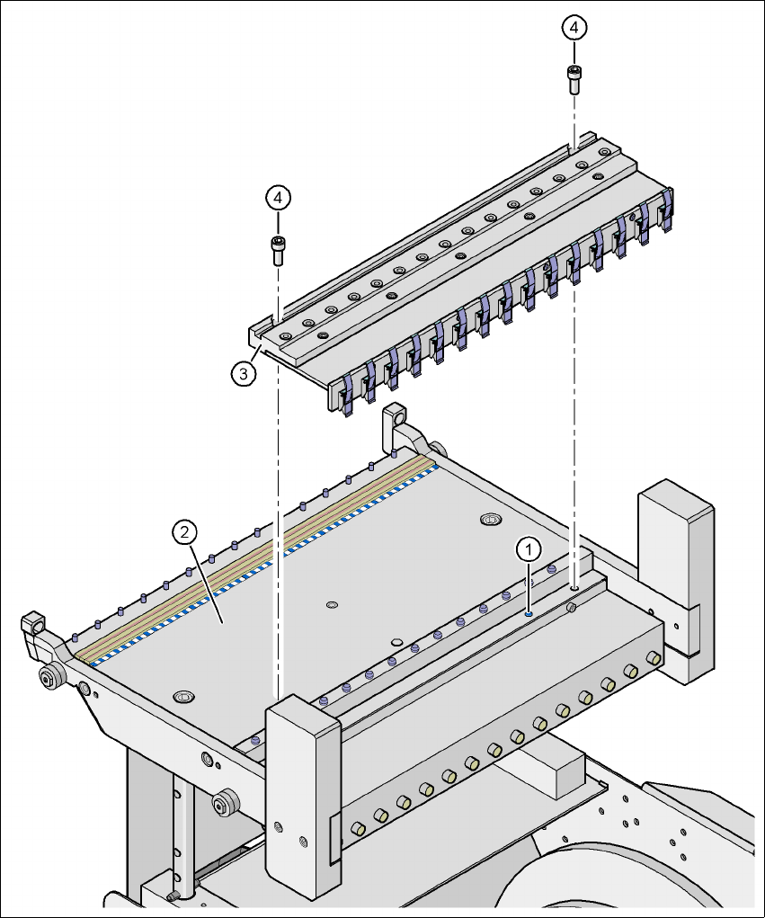
It is easy to fit. First remove the sealing plug (item 1) from the compressed air connection on the
component feeder table (item 2). Then use two screws DIN 912, M8x20 (item 4) to fix the com-
pressed air supply (item 3) to the component feeder table (item 2). The compressed air supply has
retaining clips (item 5) on the back. They fix the bulk case feeder modules to the component table
and thus ensure a perfect compressed air supply.
Option – With support for 3rd tape reel
PCB conveyor height
of the component trolley
Tape reel diameter Tape reel diameter
830 mm 17" 15"
900 mm 19" 17"
930 mm 19" 17"
950 mm 19" 19"
Mains voltage 230 VAC ± 5 %
120 VAC ± 5 %
Compressed air connection Max. 1.0 MPa (10 bar)
Output pressure Can be regulated with a valve
6 Component handling User manual SIPLACE X-Series
6.7 SIPLACE HF component trolleys Software Version SR.601.xx 11/2005 US Edition
358
6
Fig. 6.7 - 6 Compressed air supply for bulk case feeder modules, SIPLACE HF component trolley
6
(1) Sealing plug on the component feeder table
(2) Component feeder table
(3) Compressed air supply for bulk case feeder modules
(4) Screw DIN 912, M8x20
(5) Retaining clamp
User manual SIPLACE X-Series 6 Component handling
Software Version SR.601.xx 11/2005 US Edition 6.7 SIPLACE HF component trolleys
359
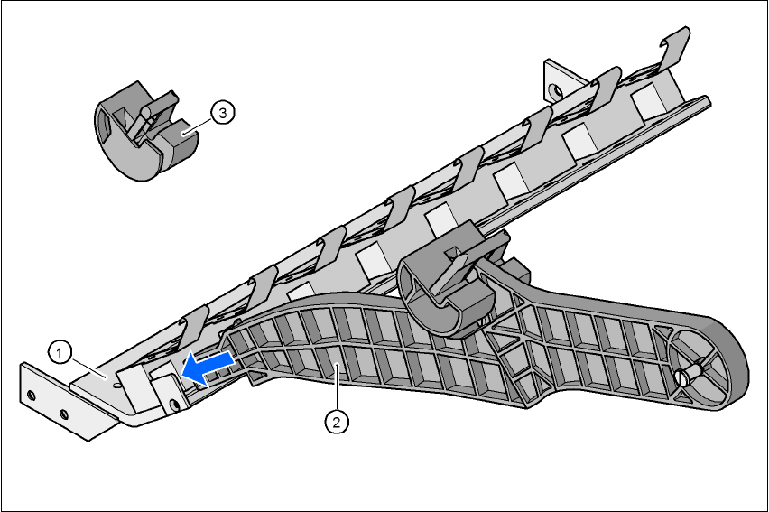
6.7.7 Mount for the middle tape reel on 3x8 mm S feeder modules
Type 3x8 mm S feeder modules transport components to the pick-up position on three feeder
tracks. The tape reels of the two outer tracks are positioned between the separating plates in the
tape container. The middle tape reel is arranged over the tape reels for the two outer tracks.
For the middle tape reels you will therefore also need:
– 1 adapter plate for holding the tape reel holder (item 1),
– for every two feeder modules, 1 tape reel holder (item 2) and
– 1 shortened idler pulley (item 3) for the tape reel holder at location 1 of the component feeder
table.
The adapter plate is fixed inside the component trolley with four fillister head screws, and the tape
reel holders are inserted into the square openings in the adapter plate.
6
Fig. 6.7 - 7 Mount for the middle tape reel on 3x8 mm S feeder modules
(1) Adapter plate
(2) Tape reel holder
(3) Idler pulley, shortened