X3_X4_Series machine.pdf - 第227页
User manual SIPLAC E X-Series 4 Setting up and commissioning Software Version SR.601.xx 11/2005 US Edition 4.4 Sett ing up the placement machine 227 4.4.1 1.5 Fitting the si de plates Æ Fix the grou nding ca ble to e ach…

4 Setting up and commissioning User manual SIPLACE X-Series
4.4 Setting up the placement machine Software Version SR.601.xx 11/2005 US Edition
226
4.4.11.3 Computer unit X2, X3 and X4 - plug-in connectors on the back panel
4
4
4.4.11.4 Fitting the computer unit
Æ Plug in the plug-in connectors on the back panel of the computer unit (see section 4.4.11.3).
Æ Carefully lift the computer unit onto the rail in the extension kit.
Æ Make sure that you do not squash any cables.
Æ Check that the cables for the front panel are in the lateral cable routing plate
(item 1 in Fig. 4.4 - 20
, page 223).
Æ Fix the cables to the front panel with cable ties.
Æ Push the computer unit into the extension kit as far as the stop.
Æ Connect the fan cable to the computer unit cable.
Æ Plug in the plug-in connectors on the front panel of the computer unit (see section 4.4.11.2).
Æ Secure the computer unit with the fillister head screw.
Æ Fix the grounding cable to the doors (item 2 in Fig. 4.4 - 16, page 217),
as shown in Fig. 4.4 - 18
on page 221.
Æ Lock the doors.
PLEASE NOTE 4
On X2 placement machines, continue from section 4.4.11.5
"Fitting the side plates".
On X3 and x4 placement machines, continue from section 4.4.12
"Installing the axis unit on X3
and X4" on page 228.
Computer unit,
back panel
(Fig. 4.4 - 21
)
Plug
Connecting cable NOTE
Plug Cable
PE1 Cable ring Grounding cable
Fix as shown in Fig. 4.4 - 18
,
page 221
.
X27pz X27pz 03003437 W1-W2 Insert as far as the stop
X2pz X2pz 03002966 W1-W5 Fix with screws
X1pz X1pz 03002969 W1-W5 Fix with screws
X62pz X62pz 03002488 Snap into place
PE2 Cable lug Grounding cable Insert as far as the stop
P24 / GND X1 Fan in extension kit Insert as far as the stop

User manual SIPLACE X-Series 4 Setting up and commissioning
Software Version SR.601.xx 11/2005 US Edition 4.4 Setting up the placement machine
227
4.4.11.5 Fitting the side plates
Æ Fix the grounding cable to each side plate (item 5 in Fig. 4.4 - 16), as shown in Fig. 4.4 - 18
page 221
.
Æ Fix the side plate to the machine frame with 6 fillister head screws.
Æ Continue from section 4.4.13 "Fitting the main fault indicator", page 230.
4 Setting up and commissioning User manual SIPLACE X-Series
4.4 Setting up the placement machine Software Version SR.601.xx 11/2005 US Edition
228
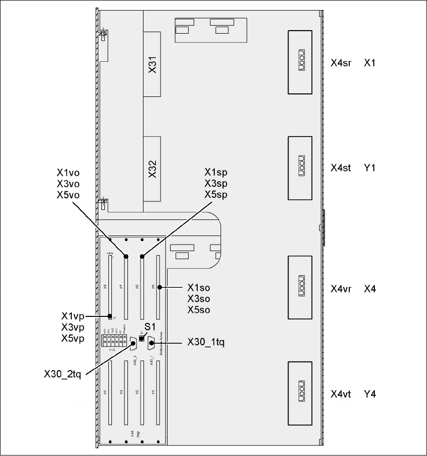
4.4.12 Installing the axis unit on X3 and X4
4.4.12.1 Axis unit X3, X4 (gantry 1 and gantry 4) - Electrical connection points
4
Fig. 4.4 - 22 Axis unit X3, X4 (gantry 1 and gantry 4), rear panel - Connecting the plugs