X3_X4_Series machine.pdf - 第265页
User manual SIPLAC E X-Series 5 Tasks on the machine Software Vers ion SR.601.xx 11/ 2005 US Ed ition 5.4 Setting up the feeder m odules 265 5.4.5 Using the S feeder module on th e component trol ley (HF-series) 5 Fig. 5…
5 Tasks on the machine User manual SIPLACE X-Series
5.4 Setting up the feeder modules Software Version SR.601.xx 11/2005 US Edition
264
Æ Push the lever (item 5 in Fig. 5.4 - 5) forward in order to raise the pick-up window (item 2 in
Fig. 5.4 - 5
) into the first latching position.
Æ Pull the cover foil at the side of the pick-up window forward and out underneath the pick-up
window.
Æ Fold the cover foil back until it lies against the pull-off edge (item 3 in Fig. 5.4 - 5).
PLEASE NOTE 5
Do not lower the pick-up window until the cover foil is lying against the pull-off edge.
Æ Push the lever (item 5 in Fig. 5.4 - 5) back to lower the pick-up window.
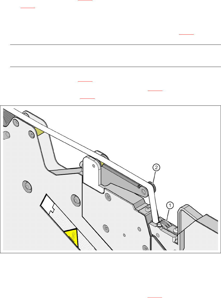
Æ Guide the cover foil over the cover foil rocker (item 2 in Fig. 5.4 - 7) until it reaches the foil
packing wheels (item 1 in Fig. 5.4 - 7
).
5
Fig. 5.4 - 7 Guiding the cover foil to the foil packing wheels
(1) Cover foil packing wheels
(2) Cover foil
5
Æ On the operator panel, press the FOIL button (item 3 in Fig. 5.4 - 6) until the cover foil is ten-
sioned. The cover foil rocker points down and stops the drive motor.
Æ Cut the component tape flush with the front end of the feeder module.
User manual SIPLACE X-Series 5 Tasks on the machine
Software Version SR.601.xx 11/2005 US Edition 5.4 Setting up the feeder modules
265
5.4.5 Using the S feeder module on the component trolley (HF-series)
5
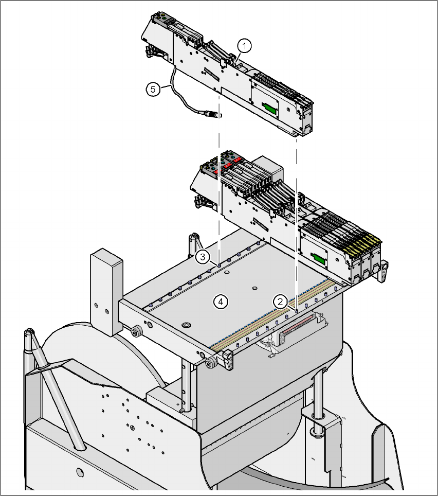
Fig. 5.4 - 8 Component trolley (HF-series) with 15 locations for S feeder modules
(1) S feeder module
(2) Centering pin
(3) Centering ball
(4) Component feeder table
(5) Connecting cable for the S feeder module
5 Tasks on the machine User manual SIPLACE X-Series
5.4 Setting up the feeder modules Software Version SR.601.xx 11/2005 US Edition
266
5.4.5.1 Preparing the component feeder table (SIPLACE HF) and S feeder modules
for set-up
Æ Clean the contact surface for the feeder module.
Æ Clean the contact surface on the component feeder table.
Æ Remove loose components from the component feeder table with a brush or use a vacuum
cleaner with appropriate nozzle.
CAUTION 5
Avoid removing components from the component table with your fingers. You may hurt your-
self with tiny splinters of metal.
5.4.6 Inserting the S feeder module
Æ First place the front of the feeder module (item 1 in Fig. 5.4 - 8), i.e. the side with the slotted
foot, onto the component feeder table (item 4 in Fig. 5.4 - 8
) so that the centering pin (item 2)
on the component feeder table slides into the slot in the feeder module foot.
Æ Then lower the back of the feeder module until the centering ball (item 3 in Fig. 5.4 - 8) dis-
appears into the hole in the feeder module.
Æ Make sure that the feeder modules are placed correctly on the component feeder table to suit
their width (see Fig. 5.4 - 9
).
Æ Check that the feeder module is firmly seated on the component feeder table.
Æ Connect the feeder module plug (item 5 in Fig. 5.4 - 8) to the socket beneath the location.
PLEASE NOTE 5
When you connect the feeder module, make sure that you use the right socket for the location
since the feeder module receives the control pulse via this socket. The feeder module may
not work correctly if it is not connected to the right socket. The user manual for the feeder
modules used will contain detailed information on the assignment of plugs to sockets.