X3_X4_Series machine.pdf - 第155页
User manual SIPLAC E X-Series 3 Technical data Software Version SR.601.xx 11/2005 US Edition 3.11 Vision cameras 155 3.1 1 V i sion cameras A compon ent ca mera is integrat ed into eac h Collec t&Place he ad (see Fig…

3 Technical data User manual SIPLACE X-Series
3.10 Gantries Software Version SR.601.xx 11/2005 US Edition
154
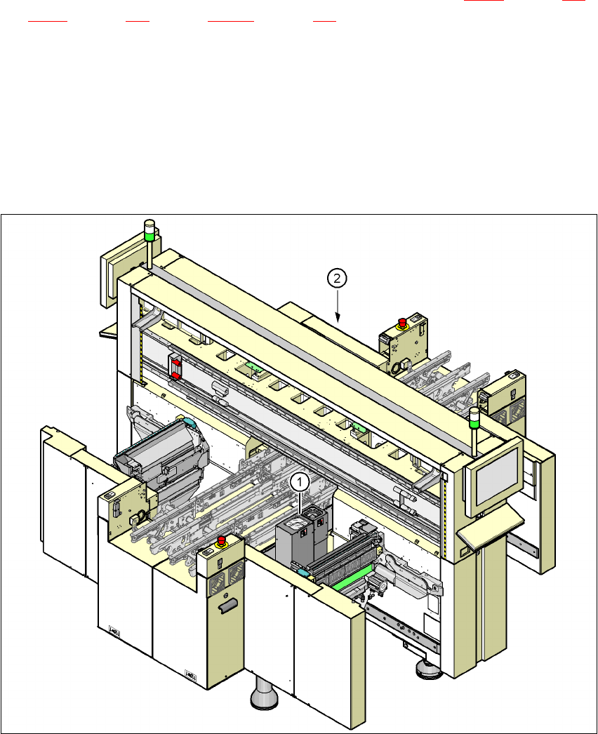
The
Y axis
essentially consists of the following main modules:
– Y-axis linear motor (primary part) (1)
– Permanent magnet (secondary part of the Y-axis linear motor) (2)
– Linear distance measuring system (3)
– Guide system (4)
– Cable and hose carrier (5)
The Y axis is driven by a linear motor. The secondary part of the drive is made up of permanent
magnets and is mounted on the machine frame. The primary part is bolted to the gantry.
3.10.7 Technical data for the Y axis
Drive Direct, linear motor
Maximum speed 2.5 m/sec.
Traversing path 1430 mm
Distance measuring system Metal linear scale
Scale length 1850 mm
Resolution 1 µm
User manual SIPLACE X-Series 3 Technical data
Software Version SR.601.xx 11/2005 US Edition 3.11 Vision cameras
155
3.11 Vision cameras
A component camera is integrated into each Collect&Place head (see Fig. 3.7 - 5 on page 121,
Fig. 3.7 - 8
on page 129 and Fig. 3.7 - 11 on page 134). The stationary P&P component vision
camera (type 33) 55 x 45 digital for the TwinHead is permanently fixed to the machine frame.
Assembly positions for the stationary P&P component camera (type 33) 55 x 45, digital 3
3
3
Fig. 3.11 - 1 Assembly positions for the stationary P&P component camera (type 33) 55 x 45, digital
(1) Assembly position for location 1 (X2 placement machine)
(2) Assembly position for location 3 (X2 and X3 placement machine)
TwinHead Stationary P&P component camera, (type 33) 55 x 45, digital
(IC camera)
Placement area 1 Location 1 (X2 placement machine)
Placement area 2 Location 3 (X2 and X3 placement machine)

3 Technical data User manual SIPLACE X-Series
3.11 Vision cameras Software Version SR.601.xx 11/2005 US Edition
156
WARNING
RISK OF HEAD CRASH 3
When the placement head is changed from the TwinHead to the Collect&Place head, the Twin-
Head's stationary component vision camera, P&P (type 33) 55 x 45, and stationary P&P compo-
nent vision camera (type 25) 16 x 16 digital must be removed, otherwise the Collect&Place head
will collide with the camera housings.
The
component vision module
is used to determine:
– the precise position of the components at the nozzle and
– the geometry of the package form.
The
PCB vision module
uses fiducials on the PCBs to determine:
– the position of the PCB,
– its rotation angle
– and the PCB skew.
The PCB cameras are fixed to the bottom of the gantries. They use fiducials on the
feeder mod-
ules
to determine the exact pick-up position of components, which is particularly important for
small components.