X3_X4_Series machine.pdf - 第54页
2 Operational safety User manual SIPLACE X-Series 2.5 Safety instru ctions for operating the mac hine Software Version S R.601.xx 11/2005 US Edition 54 2.5 Safety instructions for operatin g the machine 2.5.1 Safet y ins…
User manual SIPLACE X-Series 2 Operational safety
Software Version SR.601.xx 11/2005 US Edition 2.4 Safety instructions for transporting the machine
53
2.3.3 Laser class 2
The following modules are assigned to laser class 2:
– Laser light barrier, placement area 1 in the PCB conveyor
– Laser light barrier, placement area 2 in the PCB conveyor
– PCB barcode scanner
– Component sensor on the 20-segment Collect&Place head
– Coplanarity laser module
(The entire machine is classified as laser class 2 if the coplanarity laser module option is installed.)
2
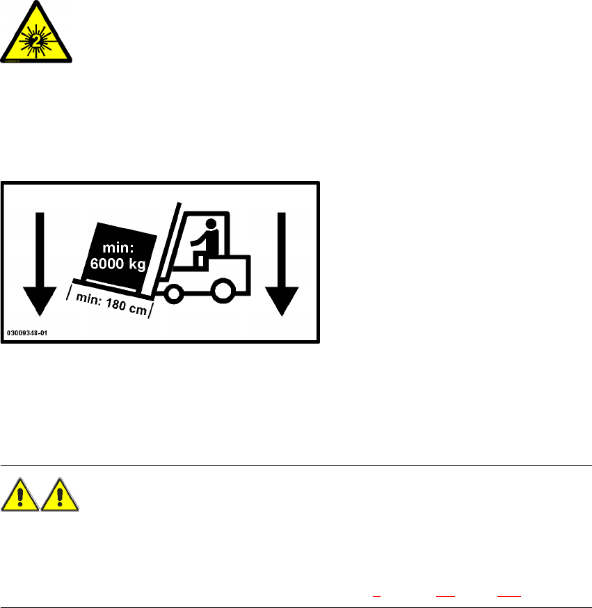
2.4 Safety instructions for transporting the machine
2
Use a fork-lift truck with the following specification to carry the machine:
Fork length: min. 1800 mm
Carrying power: min. 6000 kg
Clear width between forks: min. 350 mm 2
WARNING
RISK OF TIPPING 2
If the required specification cannot be applied to the fork-lift, there is a risk that the fork-lift will tip
over when carrying the placement machine.
Transporting the placement machine is described in chapter 4, section 4.2, page 173.
2
Laser radiation
Do not look into beam!
2 Operational safety User manual SIPLACE X-Series
2.5 Safety instructions for operating the machine Software Version SR.601.xx 11/2005 US Edition
54
2.5 Safety instructions for operating the machine
2.5.1 Safety instructions for closing the protective covers
To prevent any risk of injury when the protective covers on automatic placement machines are
closed, the owner must instruct his operators to use the protective covers exactly as specified in
the following instructions.
CAUTION
RISK OF CRUSHING HANDS
IF THE PROTECTIVE COVERS ARE NOT CLOSED CORRECTLY 2
2
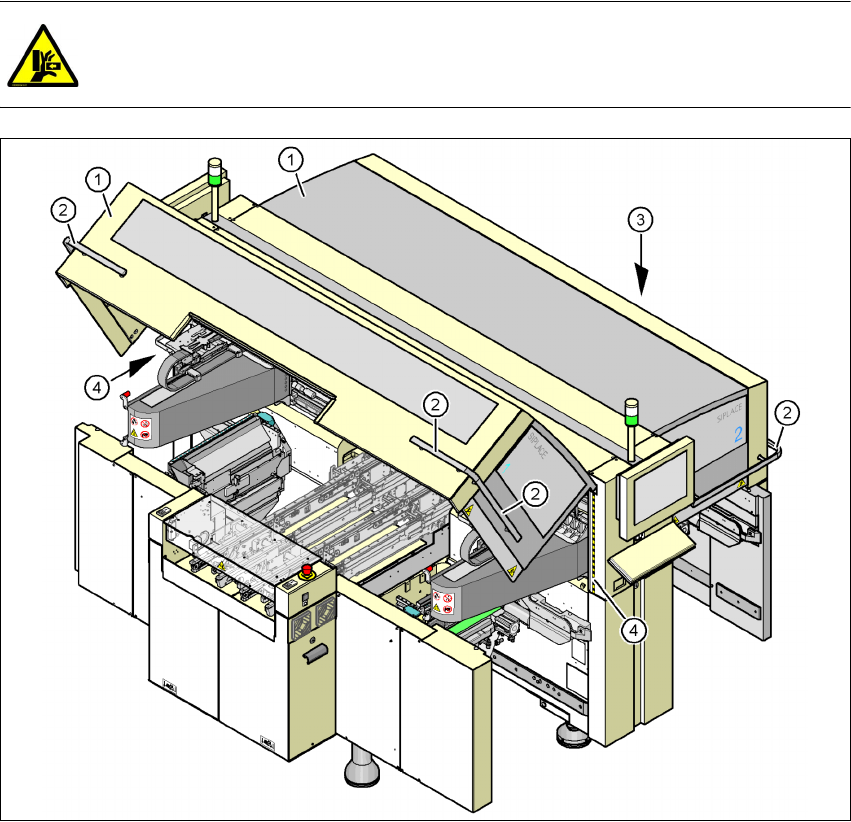
Fig. 2.5 - 1 Safety instructions for closing the protective covers
(1) Protective covers
(2) Grab handles
(3) Cover flaps over the PCB conveyor
(4) Warning strips

User manual SIPLACE X-Series 2 Operational safety
Software Version SR.601.xx 11/2005 US Edition 2.5 Safety instructions for operating the machine
55
Æ Always hold the grab handles when opening or closing the protective covers.
Æ When closing, do not reach into the gap between the protective cover and the machine panel.
The area is identified by a yellow-black warning strip (item 4 in Fig. 2.5 - 1
, page 54).
Æ When you close the covers, make sure that there is no-one else in the cover swiveling range.
Æ When you close the covers, make sure that there is no-one else in the vicinity of the opposite
component trolley location.
2.5.2 Safety instructions for processing capacitors based on powdered metal
There is a risk associated with processing capacitors based on powdered metal (e.g. tantalum).
The risk is that
– an exothermic reaction, i.e. a sudden build-up of heat, may occur, if these components are
damaged. If the ambient conditions are unfavorable, and depending on the capacitance, this
buildup of heat can cause damage.
– This effect can occur when these components are cut.
Please contact your suppliers to clarify whether the components that you handle are affected.
In extremely rare cases, this risk can occur in the tape cutter of SIPLACE machines, with the re-
mote possibility of causing a smoldering fire in the waste tape.
The ambient conditions are unfavorable if:
(1) The components remain on the tape while the set tape cycle is checked (since the operator
can cycle the feeder module onward without removing components during this check).
(2) The components remain on the tape, e.g. due to a tear in the cover foil.
(3) The components remain on the tape, and the components or tape do not conform to the spec-
ification, thus increasing the pickup error rate.
Please follow the instructions given below to minimize the risk when placing capacitors based on
powdered metal.
(1) If the component tape is cycled onward manually, the operator must remove any components
remaining in the tape pocket.
(2) If the cover foil tears, the operator must remove any components remaining on the tape.
PLEASE NOTE 2
The manual extraction by the operator of tantalum capacitors that have not been picked up is
described in section 6.6.1 on page 329.