X3_X4_Series machine.pdf - 第412页
7 Station extensions User manual SIPLACE X-S eries 7.3 Component c amera for the TwinHead, FC came ra Software Version SR. 601.xx 11/2005 US Edition 412 7.3.1.1 Pos ition of the component vision cameras for the T winHead…
User manual SIPLACE X-Series 7 Station extensions
Software Version SR.601.xx 11/2005 US Edition 7.3 Component camera for the TwinHead, FC camera
411
7.3 Component camera for the TwinHead, FC camera
7.3.1 Stationary P&P component camera (type 25) 16 x 16, digital (FC camera)
Item no. 00119718-xx
7
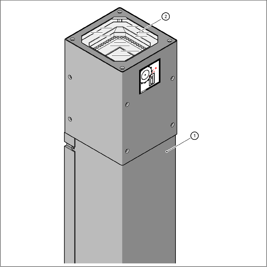
Fig. 7.3 - 1 Stationary P&P component camera (type 25) 16 x 16, digital (FC camera)
(1) Camera housing with integral camera and camera amplifier
(2) Glass plate - over the illumination and lens levels
7
7 Station extensions User manual SIPLACE X-Series
7.3 Component camera for the TwinHead, FC camera Software Version SR.601.xx 11/2005 US Edition
412
7.3.1.1 Position of the component vision cameras for the TwinHead on the
X3 placement machine
7
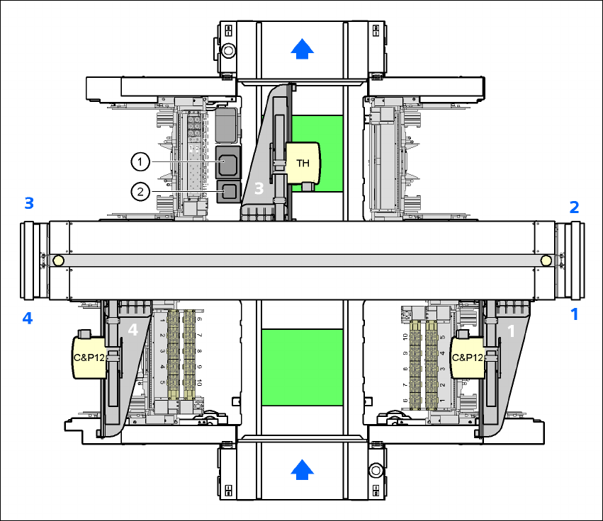
Fig. 7.3 - 2 Position of the component vision cameras for the TwinHead on the X3 placement machine
(1) Assembly position for the CO vision camera (stationary, P&P (type 33) 55 x 45), location 3
(2) Assembly position for the CO vision camera (stationary, P&P (type 25) 16 x 16), location 3
User manual SIPLACE X-Series 7 Station extensions
Software Version SR.601.xx 11/2005 US Edition 7.3 Component camera for the TwinHead, FC camera
413
7.3.1.2 Position of the component vision cameras for the TwinHead on the
X2 placement machine
7
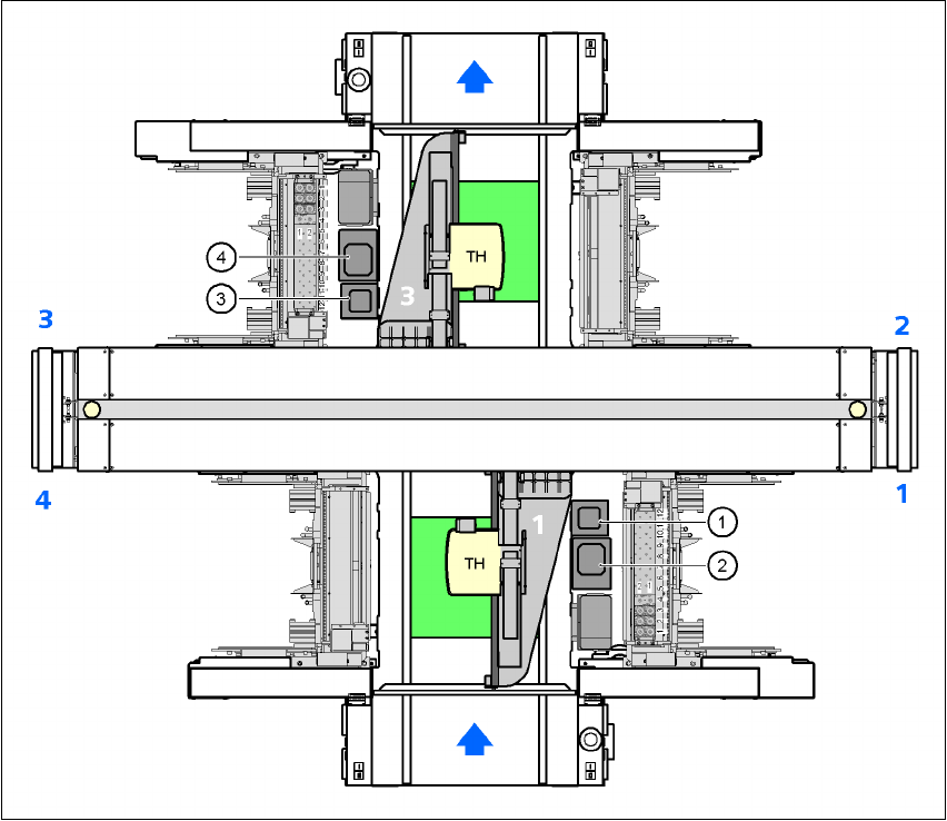
Fig. 7.3 - 3 Position of the component vision cameras for the TwinHead on the X2 placement machine
(1) Assembly position for the CO vision camera (stationary, P&P (type 25) 16 x 16), location 1
(2) Assembly position for the CO vision camera (stationary, P&P (type 33) 55 x 45), location 1
(3) Assembly position for the CO vision camera (stationary, P&P (type 25) 16 x 16), location 3
(4) Assembly position for the CO vision camera (stationary, P&P (type 33) 55 x 45), location 3