X3_X4_Series machine.pdf - 第302页
6 Component handling User manual SIPLACE X-Series 6.1 X feeder modules for the c omponent trolley fro m the SIPLACE X-series Software Version SR. 601.xx 11/2005 US Edition 302 6.1.3 W affle-p ack tray holder for the com …
User manual SIPLACE X-Series 6 Component handling
Software Version SR.601.xx 11/2005 US Edition 6.1 X feeder modules for the component trolley from the SIPLACE X-series
301
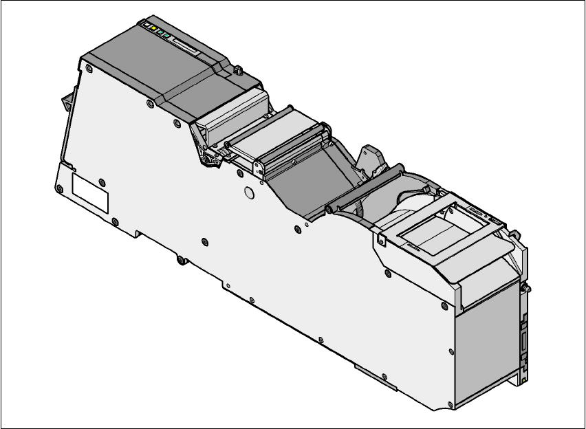
6.1.2.9 88 mm X tape feeder module
6
Fig. 6.1 - 13 88 mm X tape feeder module
6
6
6
88 mm X tape feeder module Item no. 00141278-xx
88 mm X tape feeder module with splice sensor Item no. 00141298-xx
Width 105.2 mm
Feeder module locations filled 9
Conveyor increment From 4 mm to 96 mm in 4 mm increments
Changeover time for the component tape < 45 s
Changeover time for the pre-set feeder module
on the machine
< 15 s
6 Component handling User manual SIPLACE X-Series
6.1 X feeder modules for the component trolley from the SIPLACE X-series Software Version SR.601.xx 11/2005 US Edition
302
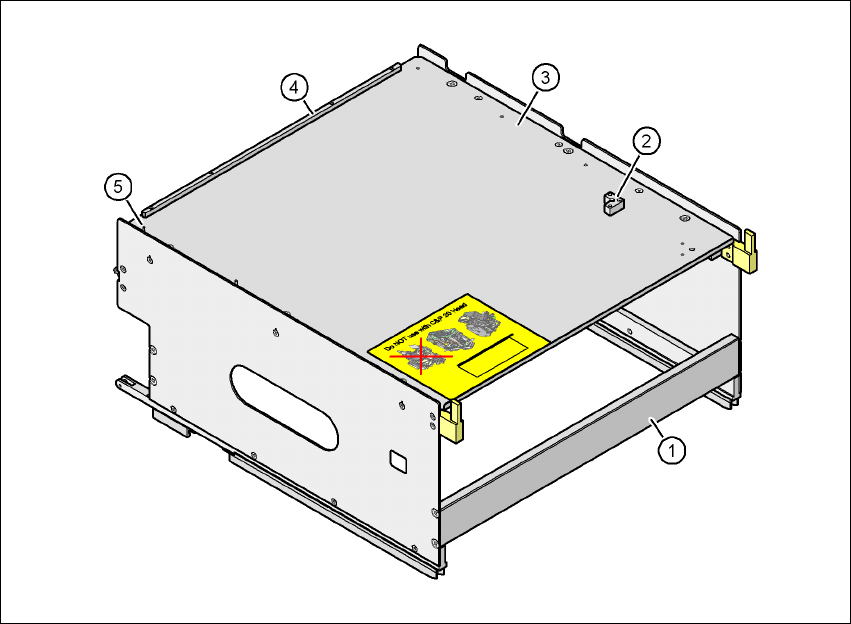
6.1.3 Waffle-pack tray holder for the component trolley from the SIPLACE X-series
Item no. 00141285-xx
6
Fig. 6.1 - 14 Waffle-pack tray holder
(1) Waffle-pack tray holder from the SIPLACE X-series
(2) Retaining bracket for a second JEDEC waffle-pack tray
(3) Waffle-pack tray carrier
(4) Stop bars for the JEDEC waffle-pack tray
(5) Dowel pin - Zero point for the JEDEC waffle-pack tray
Individually fitted JEDEC waffle-pack trays or waffle-pack magazines can be fixed to the waffle-
pack tray carrier using magnets. If two JEDEC waffle-pack trays are fitted, you must fix them with
locking and retaining rails, as used for the waffle-pack tray carrier on the MTC2.
Parts Item no.
Magnet 00316593-xx
Locking and retaining rail for JEDEC trays 00372615-xx

User manual SIPLACE X-Series 6 Component handling
Software Version SR.601.xx 11/2005 US Edition 6.1 X feeder modules for the component trolley from the SIPLACE X-series
303
6.1.3.1 Technical data
*) X feeder modules can be positioned at the remaining 8 locations. If locking and retaining rails
are used, however, the fixing lever projecting at the side reduces the available locations to 6.
6.1.3.2 Number of waffle-pack trays per location and machine
6.1.3.3 Using the waffle-pack tray holder on the X-series component trolley
Æ Place the two front slider guides (item 1 in Fig. 6.1 - 15, page 304) of the holder on the inser-
tion aid (item 6).
Æ Push the holder forward along the guide profiles (item 7). The holder will slide with its front
(item 1) and rear slider guides (item 2) on the guide profiles.
Æ Carefully push the holder further until the two "front" centering pins (item 4) disappear into the
centering holes (item 10).
Æ Watch the two "rear" centering pins (item 3) on the holder. They must slide easily into the re-
cesses (item 8) on the centering bar.
Æ When the holder is at the stop position, the locking tabs (item 9) engage on the locking rollers
(item 5) on the holder.
The waffle-pack tray holder can be locked and released via the user interface. It is therefore not
possible to change the holder while placement is in progress.
Dimensions L x W x H 429 mm x 376 mm x 200 mm
Location filled on the component table 32 locations
*)
Positioning option on the X-series machines Locations 2 and 4
Software
Station software SR.601.xx or later
Programming system SIPLACE Pro 3.0 or later
Range of placement heads TwinHead, C&P6, C&P12
Placement machine Location 2 Location 4
X4 1 1
X3 2 1
X2 2 2