X3_X4_Series machine.pdf - 第322页
6 Component handling User manual SIPLACE X-Series 6.5 Docking station for the component tr olley from the SIPLA CE X-series Sof tware Version SR. 601.xx 11/2005 US Edition 322 6.5.4 Adapting the component trolley docking…
User manual SIPLACE X-Series 6 Component handling
Software Version SR.601.xx 11/2005 US Edition 6.5 Docking station for the component trolley from the SIPLACE X-series
321
6
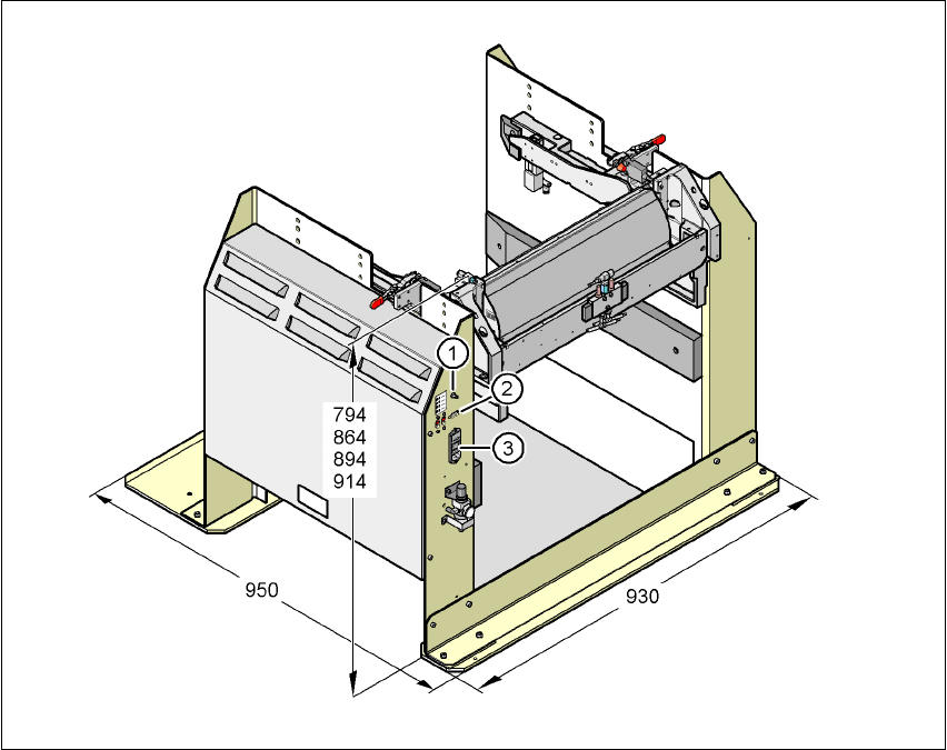
Fig. 6.5 - 2 Docking station - Dimensions in millimeters, connection points
(1) Compressed air connection
(2) CAN bus connection
(3) Power supply connection
6 Component handling User manual SIPLACE X-Series
6.5 Docking station for the component trolley from the SIPLACE X-series Software Version SR.601.xx 11/2005 US Edition
322
6.5.4 Adapting the component trolley docking unit to the PCB conveyor height
The X-series component trolley docking unit can be set to the following PCB conveyor heights with
just a few simple actions:
830 mm ± 15 mm Standard height
900 mm ± 15 mm SMEMA height
930 mm ± 15 mm SMEMA height
950 mm ± 15 mm SMEMA height
6
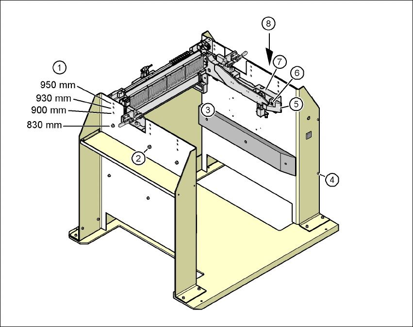
Fig. 6.5 - 3 Adapting the component trolley docking unit to the PCB conveyor heights
(1) Holes for the PCB conveyor height
(2) Hexagonal nut M8 and washer, 6x
(3) Hexagon socket head screw M8x40, 6x
(4) Hexagon socket head screw M5x12, 4x
(5) Guide
(6) Hexagon socket head screw M8x18, 2x
(7) Component trolley docking unit
(8) Panel
User manual SIPLACE X-Series 6 Component handling
Software Version SR.601.xx 11/2005 US Edition 6.5 Docking station for the component trolley from the SIPLACE X-series
323
6.5.4.1 Tools
You will need the following tools and equipment to adjust the height for the component trolley
docking unit:
– Allen key, set
– Fork wrench, size 13
6.5.4.2 Converting the component trolley docking unit to other heights
WARNING 6
Æ Disconnect the docking station from the main power supply.
Æ Disconnect the docking station from the compressed air supply
A second person will be needed to help with the conversion due to the weight of the component
trolley docking unit.
Æ Remove the two hexagon socket head screws M8x18 (item 6 in Fig. 6.5 - 3, page 322) and
remove the left and right guides (item 5 in Fig. 6.5 - 3
).
6
PLEASE NOTE: 6
Only remove the panel (item 8 in Fig. 6.5 - 3
) in the following situations:
– You are converting the component trolley docking unit to a height of 830 mm.
– You are converting the component trolley docking unit from the height of 830 mm to a different
height.
Æ Remove the 4 hexagon socket head screws M5x12. Hold the panel tightly so that it does not
drop down.
Æ Remove the panel.
Æ Loosen the 6 hexagonal nuts M8 (item 2 in Fig. 6.5 - 3, page 322) and the 6 washers.
Æ Now ask a second person to hold the component trolley docking unit while you remove the 6
hexagon socket head screws M8x40 (item 3 in Fig. 6.5 - 3
).
Æ Position the component trolley docking unit (item 7 in Fig. 6.5 - 3) at the required height
(item 1).