X3_X4_Series machine.pdf - 第375页
User manual SIPLAC E X-Series 7 Station extensions Software Vers ion SR.601.xx 11/ 2005 US Ed ition 7.1 Nozzle changer 375 7.1.1.4 T echnical dat a 7 7.1.1.5 Assembly "Row 1" no zzle c hangers (see Figs. 7.1 - …
7 Station extensions User manual SIPLACE X-Series
7.1 Nozzle changer Software Version SR.601.xx 11/2005 US Edition
374
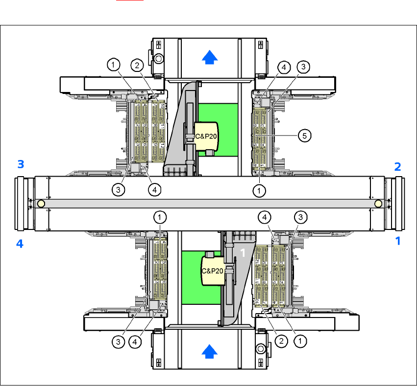
7.1.1.3 Position of the nozzle changers for the C&P20 head on the X2 machine
1 or 2 nozzle changers may be installed at locations 1, 3, and 4 for the 20 segment Collect&Place
head (items 1 and 2 in Fig. 7.1 - 3
). One nozzle changer may be installed at location 2. This gives
a total capacity of 6 nozzle changers with 36 magazines and a total of 432 nozzle holders.
7
Fig. 7.1 - 4 Position of the nozzle changer for the 20-segment Collect&Place head on the X2 machine
7
(1) Nozzle changer, "row 1"
(2) Nozzle changer, "row 2"
(3) Reject bin for components
(4) Take-off device and reject bin for nozzles
(5) Nozzle magazine
User manual SIPLACE X-Series 7 Station extensions
Software Version SR.601.xx 11/2005 US Edition 7.1 Nozzle changer
375
7.1.1.4 Technical data
7
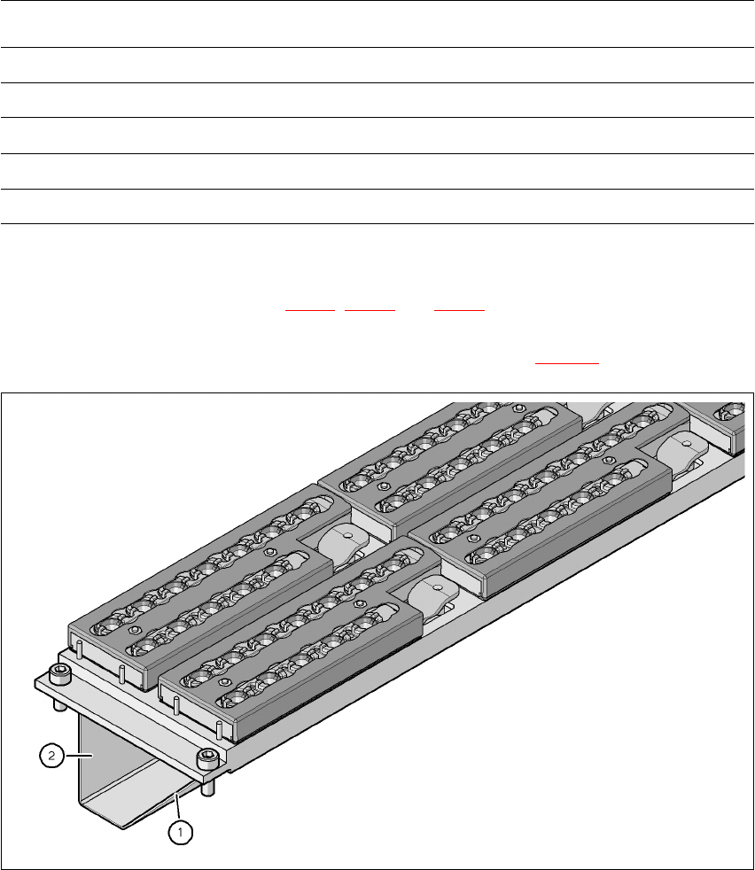
7.1.1.5 Assembly
"Row 1" nozzle changers (see Figs. 7.1 - 3, 7.1 - 2 and 7.1 - 4) are each fixed to the component
trolley docking unit. There is an additional assembly kit for the "row 2" nozzle changer. This kit
consists of the take-off device and the nozzle reject bin (see section 7.1.1.10
).
7
Fig. 7.1 - 5 Assembly position
(1) Sloping side points towards the component trolley docking unit
(2) Vertical side points towards the PCB conveyor
Æ Align the nozzle changer so that the sloping side points towards the component trolley dock-
ing unit.
Nozzle changer for the 20-segment Collect&Place head
Dimensions (length x width x height) 449 x 94,5 x 79 mm³
Number of nozzle holders 72
Nozzle types 10xx, 11xx and 12xx
Time required to open and close the locking plate < 200 ms
Compressed air connection 0.48 MPa (4.8 bar)
7 Station extensions User manual SIPLACE X-Series
7.1 Nozzle changer Software Version SR.601.xx 11/2005 US Edition
376
WARNING 7
Only install the associated nozzle changer for each placement head. There is a risk of head
crashes with mixed configurations.
7.1.1.6 Description of the functions
The nozzles are seated in nozzle holders and are held in place by a movable locking plate. A
pneumatic cylinder moves the locking plate 7 mm. All the nozzles are either clamped or released,
depending on the position of the locking plate. The default position of the locking plate, i.e. if there
is no nozzle change in progress, is "closed".
Each magazine on the nozzle changer has two positioning fiducials for detecting the position and
orientation of the magazine. The magazine locations are numbered consecutively from 1 - 6 for
the "row 1" nozzle changers and from 7 - 12 for the "row 2" (see Figs. 7.1 - 3
, 7.1 - 2 and 7.1 - 4).
The 12 nozzle garages in the magazines are numbered consecutively (see Fig. 7.1 - 8
).
PLEASE NOTE 7
Special magazines are available upon request (contact SIEMENS A&D for details) and will be
numbered differently.
Picking up a nozzle 7
– The Collect&Place head Z axis moves down.
– The locking plate (item 2 in Fig. 7.1 - 6
) opens and releases the nozzles.
– The nozzle is picked up by the sleeve of the Collect&Place head.
– The Z axis moves up.
Setting down a nozzle 7
– The locking plate (item 2 in Fig. 7.1 - 6) opens and releases the nozzles.
– The Collect&Place head Z axis moves down and sets the nozzle down.
– The locking plate closes.
– The Collect&Place head Z axis moves up.
Discarding defective nozzles 7
– The Collect&Place head Z axis moves down towards the discarding device (item 4 in Figs.
7.1 - 2
, 7.1 - 3 and 7.1 - 4) and thus moves the defective nozzle into the opening in the dis-
carding device. The opening is sized so that the nozzle can no longer be turned. The turning
motion of the DP axis detaches the nozzle from the sleeve.