X3_X4_Series machine.pdf - 第325页
User manual SIPLAC E X-Series 6 Component han dling Software Version SR.601.xx 11/2005 US Edition 6.5 Docking station for the component trolley from the SIPLACE X-series 325 6.5.5 Controls and displays 6 Fig. 6.5 - 4 Doc…
6 Component handling User manual SIPLACE X-Series
6.5 Docking station for the component trolley from the SIPLACE X-series Software Version SR.601.xx 11/2005 US Edition
324
CAUTION 6
Be careful not to damage any cables while raising and lowering the component trolley docking
unit.
Æ Insert the 6 hexagon socket head screws M8x40 (item 3 in Fig. 6.5 - 3) into the holes in the
component trolley docking unit and docking station.
Æ Tighten the screws of the component trolley docking unit with the 6 M8 nuts and washers
(item 2 in Fig. 6.5 - 3
, page 322).
Æ Fix the left and right guides (item 5 in Fig. 6.5 - 3) using the hexagon socket head screw
M8x18 (item 6 in Fig. 6.5 - 3
).
Æ If necessary, fix the panel (item 8 in Fig. 6.5 - 3) with the 4 hexagon socket head screws
M5x12.
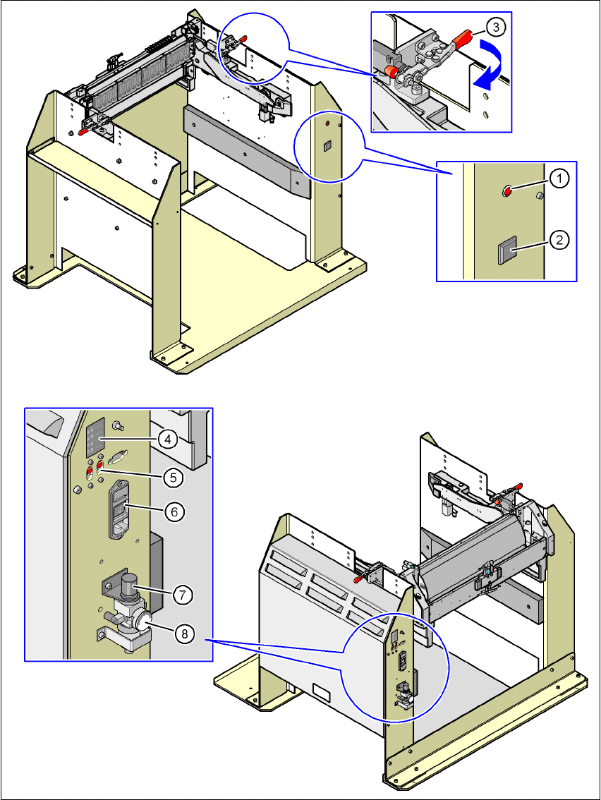
Key to fig. 6.5 - 4
(1) Main power supply indicator lamp
(2) Button for locking and releasing all the feeder modules on the component trolley
(3) Horizontal tensioner for fixing the component table lever in the "closed" position
(4) Label showing switches S1 and S2 for CAN bus addressing
(5) Switches S1 and S2 for setting the CAN bus address
(6) Power switch
(7) Rotary knob for setting the operating pressure
(8) Manometer for displaying the operating pressure
User manual SIPLACE X-Series 6 Component handling
Software Version SR.601.xx 11/2005 US Edition 6.5 Docking station for the component trolley from the SIPLACE X-series
325
6.5.5 Controls and displays
6
Fig. 6.5 - 4 Docking station - Controls and displays
6 Component handling User manual SIPLACE X-Series
6.5 Docking station for the component trolley from the SIPLACE X-series Software Version SR.601.xx 11/2005 US Edition
326
6.5.6 Starting up the docking station
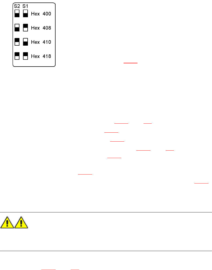
6.5.6.1 Setting the CAN bus address
6
Fig. 6.5 - 5 Docking station, addresses
6
6
6.5.6.2 Switching on the docking station
Æ Connect the compressed air line (item 1 in Fig. 6.5 - 2, page 321).
Æ Connect the CAN bus cable (item 2 in Fig. 6.5 - 2).
Æ Connect the main power cable (item 3 in Fig. 6.5 - 2).
Æ Switch the docking station on at the switch (item 6 in Fig. 6.5 - 4, page 325).
The red power indicator lamp (item 1 in Fig. 6.5 - 4
) should light up.
Æ Check the operating pressure.
The manometer (item 8 in Fig. 6.5 - 4
) should read around 0.5 MPa (5 bar).
Æ If necessary, adjust the operating pressure by turning the rotary knob (item 7 in Fig. 6.5 - 4).
6.5.7 Docking the SIPLACE X-series component trolley into the docking station
WARNING 6
Æ Only component trolleys from the SIPLACE X-series may be operated at this docking station.
Æ While docking, do not reach into the areas between component trolley and docking station.
Æ Release the two horizontal tensioners by moving them in the direction indicated by the arrow
(item 3 in Fig. 6.5 - 4
, page 325).
Up to 4 docking stations can be connected to the PC via a CAN
bus cable.
– Make sure that you do not assign CAN bus
addresses to docking stations connected to one
another more than once.
– For each docking station, set the address using
switches S1 and S2
(item 5 in Fig. 6.5 - 4
) as shown opposite.