X3_X4_Series machine.pdf - 第19页
User manual SIPLAC E X-Series 1 Introduction Software Version SR.601.xx 11/2005 US Edition 1.1 Description 19 1.1.2 SIPLACE X3 The X3 plac ement ma chine has 3 gantrie s, 2 of which a re in placem ent area 1 an d one is …

1 Introduction User manual SIPLACE X-Series
1.1 Description Software Version SR.601.xx 11/2005 US Edition
18
1.1 Description
The placement systems from the SIPLACE X-series are particularly suitable for applications that
demand a high level of flexibility, utmost precision and high placement rate. Two placement meth-
ods are used:
– the Collect & Place method for high-speed placement of standard components
– the Pick & Place method for fast placement of special fine-pitch and super-fine pitch compo-
nents
The SIPLACE principle 1
The moving head picks up the components from their stationary feeder, and places them on the
PCB, which is also stationary. This proven SIPLACE principle has many advantages:
– Short down times for refilling or splicing
– Even the smallest components (e.g. 0201) are picked up reliably
– The components cannot slip on the PCB
– Minimal traversing paths
High flexibility, cost-effectiveness and set-up reliability combine to ensure that the SIPLACE series
placement machines provide high productivity. Minimum down times increase utilization and thus
help to increase productivity.
1.1.1 SIPLACE X4
The X4 placement machine is equipped with gantries, two gantries for each placement area (PA).
All the gantry axes are driven by linear motors. The gantry axes can be positioned quickly and
accurately in the X and Y directions. The gantry arms are lightweight constructions made from a
highly rigid carbon fiber composite material. There is a placement head on each gantry. The fol-
lowing placement head configurations are possible:
*) Placement area 1
**) Placement area 2
The performance data can be found in section 3.2 on page 96.
1
PA1
*)
Placement heads
PA2
**)
C&P20/C&P20 C&P12/C&P12 C&P12/C&P6 C&P6/C&P6
Placement
heads
C&P20 / C&P20 yes no no no
C&P12 / C&P12 yes yes no no
C&P12 / C&P6 yes yes yes no
C&P6 / C&P6 yes yes yes yes

User manual SIPLACE X-Series 1 Introduction
Software Version SR.601.xx 11/2005 US Edition 1.1 Description
19
1.1.2 SIPLACE X3
The X3 placement machine has 3 gantries, 2 of which are in placement area 1 and one is in place-
ment area 2. This allows the following placement head configurations:
*) Placement area 1
**) Placement area 2
The performance data can be found in section 3.2 on page 96.
1.1.3 SIPLACE X2
The X2 placement machine has one gantry per placement area. The following placement head
configurations are possible:
*) Placement area 1
**) Placement area 2
The performance data can be found in section 3.2 on page 96.
1
PA1
*)
Placement heads
PA2
**)
C&P20/C&P20 C&P12/C&P12 C&P12/C&P6 C&P6/C&P6
Placement
heads
C&P20 yes no no no
C&P12 yes yes no no
C&P6 yes yes yes yes
TH yes yes yes yes
1
PA1
*)
Placement heads
PA2
**)
C&P20 C&P12 C&P6 TH
Placement
heads
C&P20 yes no no no
C&P12 yes yes no no
C&P6 yes yes yes no
TH yes yes yes yes
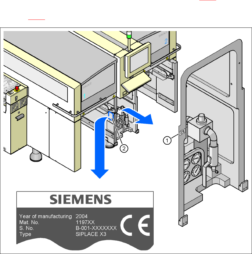
1 Introduction User manual SIPLACE X-Series
1.2 Serial number of the placement machine Software Version SR.601.xx 11/2005 US Edition
20
1.2 Serial number of the placement machine
The serial number of the placement machine can be found in two different places.
– The serial number, without leading zeroes, e.g. B-1, is struck on the left-hand side of the ma-
chine frame, on the same side as the pneumatic unit (see item 1 in Fig. 1.2 - 1
).
– With leading zeros, e.g. B-001, the serial number is punched in the rating plate (see item 2 in
figure 1.2 - 1
).
1
Fig. 1.2 - 1 Places with the serial number on the machine