X3_X4_Series machine.pdf - 第58页
2 Operational safety User manual SIPLACE X-Series 2.5 Safety instru ctions for operating the mac hine Software Version S R.601.xx 11/2005 US Edition 58 2.5.5 Safety instru ctions for the T winHead component cameras durin…
User manual SIPLACE X-Series 2 Operational safety
Software Version SR.601.xx 11/2005 US Edition 2.5 Safety instructions for operating the machine
57
2.5.4 Safety instructions for manually moving the Z axis at the TwinHead
CAUTION
RISK OF CRUSHING AT THE TWINHEAD 2
NEVER move the Z axis down with your hand at the buffer of the return unit. The powerful spring
force of the cylinder creates a risk of injury to your fingers due to the buffer springing back. The
same applies inside the TwinHead when the piston rod springs back into its starting position.
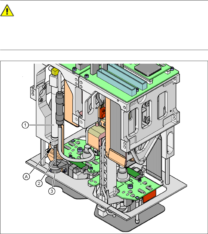
Fig. 2.5 - 3 Risk of crushing from the return unit on the TwinHead
(1) Return unit, compressed air cylinder
(2) Piston rod
(3) Buffer of the return unit
(A) Risk of crushing to fingers
2 Operational safety User manual SIPLACE X-Series
2.5 Safety instructions for operating the machine Software Version SR.601.xx 11/2005 US Edition
58
2.5.5 Safety instructions for the TwinHead component cameras during
a placement head change
WARNING 2
When the placement head is changed from the TwinHead to the Collect&Place head, the Twin-
Head's component cameras (stationary, P&P, type 33, 55 x 45, and type 25, 16 x 16) must be
removed, otherwise the Collect&Place head will collide with the camera housings.
2
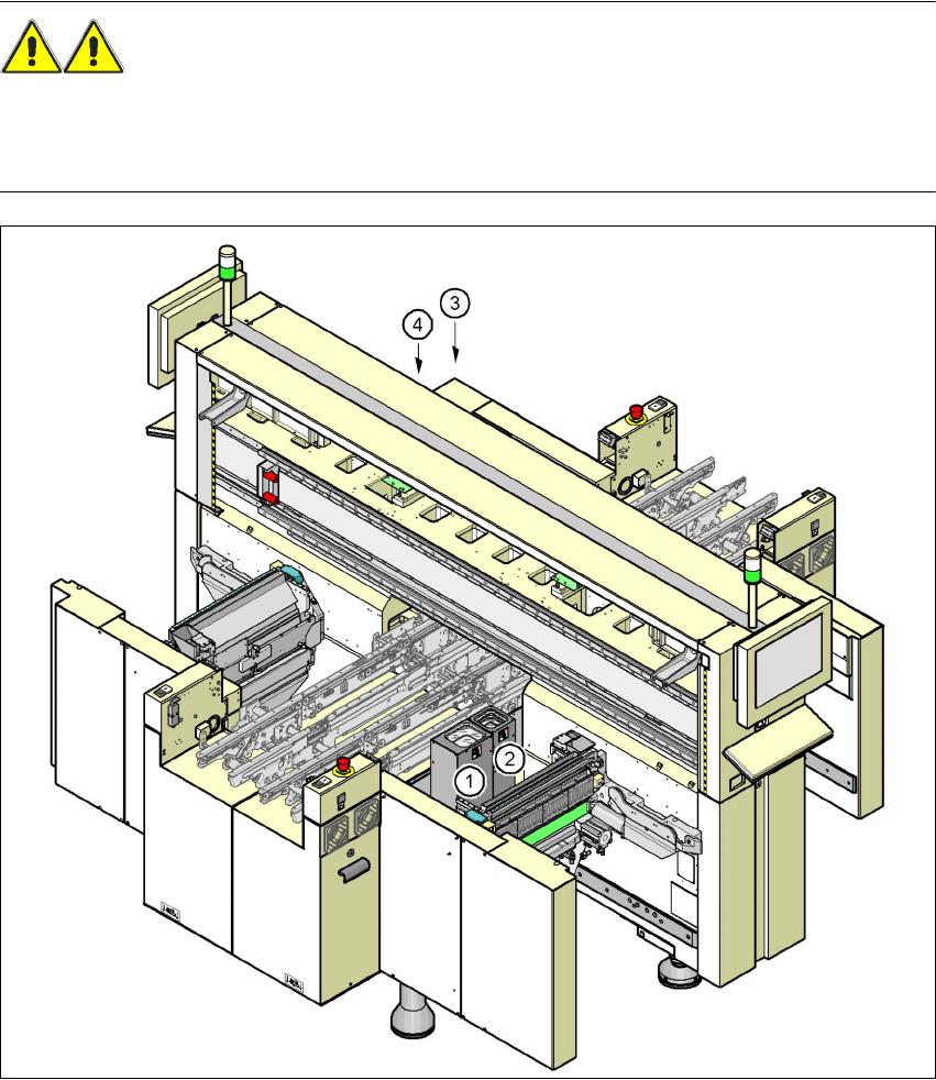
Fig. 2.5 - 4 Safety instructions for the TwinHead vision modules during a placement head change
(1) Assembly position, component camera (stationary, P&P (type 33) 55 x 45), location 1 (X2)
(2) Assembly position, component camera (stationary, P&P (type 25) 16 x 16), location 1 (X2)
(3) Assembly position, component camera (stationary, P&P (type 33) 55 x 45), location 3 (X2 and X3)
(4) Assembly position, component camera (stationary, P&P (type 25) 16 x 16), location 3 (X2 and X3)
User manual SIPLACE X-Series 2 Operational safety
Software Version SR.601.xx 11/2005 US Edition 2.5 Safety instructions for operating the machine
59
2.5.6 Safety instructions for docking the component trolley in or out
WARNING
To prevent accidents (risk of crushing), the component trolley may only be docked in or out by
one person.
2
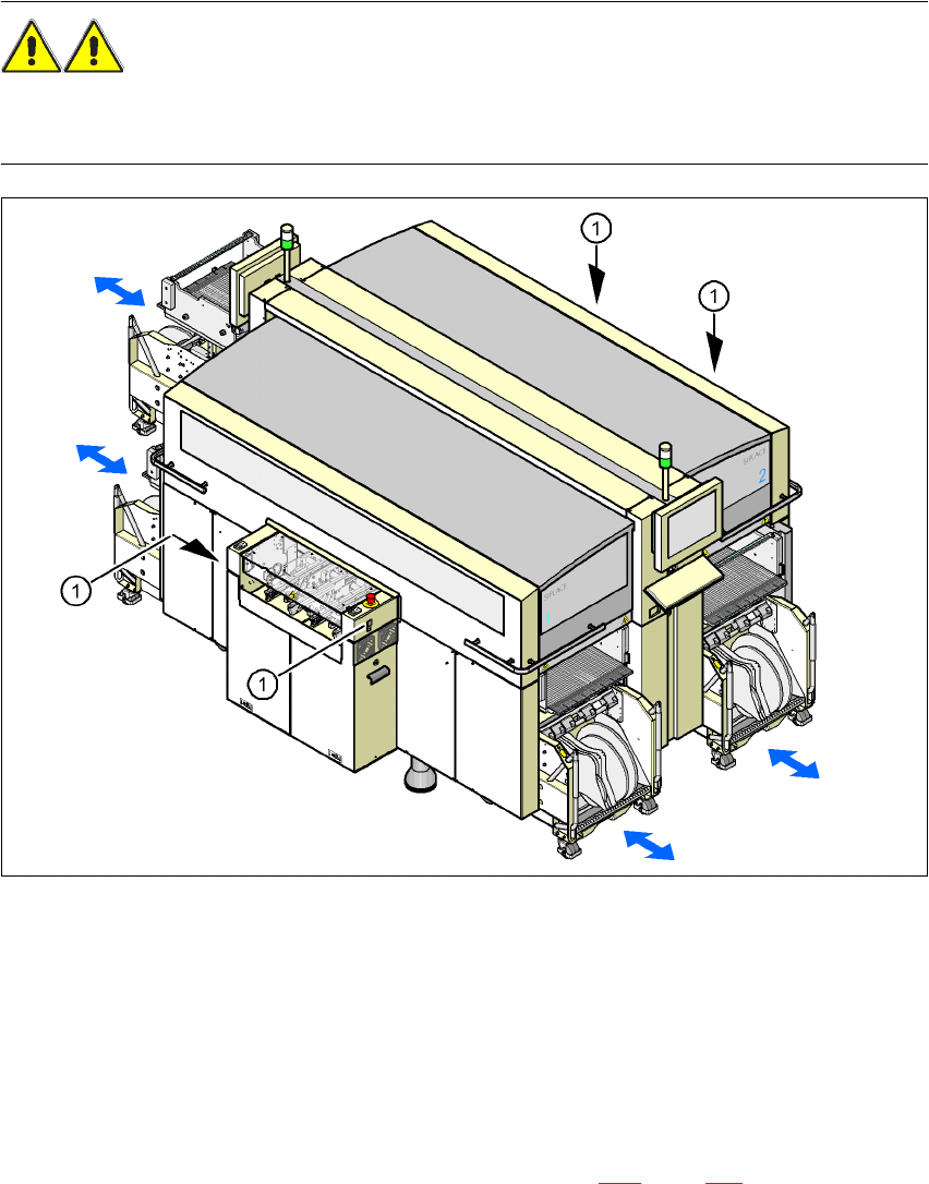
Fig. 2.5 - 5 Safety instructions for docking the component trolley in or out
2
(1) Buttons on the input and output sides
2
The safety concept for the component trolley change requires the operator to press a button
(item 1) on the input or output side of the machine in order to dock the component trolley in or out.
This ensures that the operator is always standing to the side of the placement machine. In addi-
tion, the component trolley can only be docked in if the protective covers are closed.
Docking the component trolley in or out is described in Section 5.10
, page 275. Follow the instruc-
tions exactly as described in this section.