X3_X4_Series machine.pdf - 第144页
3 Technical data User manual SIPLACE X-Series 3.9 Controls Software Version S R.601.xx 11/2005 US Edition 144 3.9 Controls 3.9.1 Controls and displays 3 Fig. 3.9 - 1 Controls and displays (1) Operat or panel on th e powe…
User manual SIPLACE X-Series 3 Technical data
Software Version SR.601.xx 11/2005 US Edition 3.8 Electrical and pneumatic connection points
143
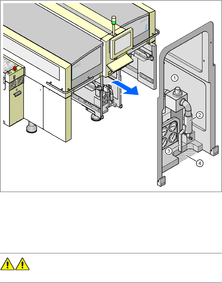
3.8.2 Pneumatic connection point
Fig. 3.8 - 2 Pneumatic connection point on the placement machine
3
(1) Pneumatic unit
(2) Coupling for connecting the compressed air hose
(3) Stop valve
(4) Recess for the air hose
WARNING
NEVER detach compressed air lines while they are still pressurized. Risk of injury. 3
3 Technical data User manual SIPLACE X-Series
3.9 Controls Software Version SR.601.xx 11/2005 US Edition
144
3.9 Controls
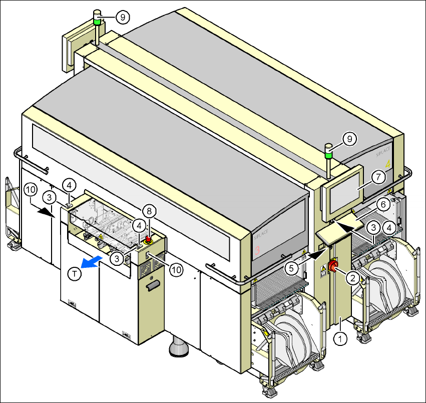
3.9.1 Controls and displays
3
Fig. 3.9 - 1 Controls and displays
(1) Operator panel on the power supply side (7) LCD touchscreen
(2) Main power switch (8) Emergency stop button
(3) Stop button (black) (9) Indicator lamps
(4) Start button (white) (10) Buttons for docking the component
trolley in and out
(5) Component counter
(6) Keyboard (T) Direction of PCB transport
User manual SIPLACE X-Series 3 Technical data
Software Version SR.601.xx 11/2005 US Edition 3.9 Controls
145
3.9.2 Description
All the controls can be reached by a 1.60 m tall person.
Main power switch 3
The main power switch is used to switch the power supply to the placement machine on and off.
WARNING
Some parts inside the placement machine carry potentially lethal voltages - even when switched
off at the main power switch. 3
Stop button 3
This button is used to stop the placement machine.
Start button 3
This button starts the placement machine after it has been switched on or after faults have been
eliminated.
Emergency stop button 3
The emergency stop button latches in the ON position when pressed. The power supply to the
gantry axes, the component trolleys, conveyors and used tape cutters is interrupted and the volt-
age supplied to the star axes of the placement heads is reduced. Turn the button to release it.
Component counter 3
The component counter displays the number of components processed in increments of ten.
LCD touchscreen 3
There is a flat LCD screen with a touch-sensitive surface (touchscreen) on either side of the place-
ment machine.
Keyboard 3
The keyboard is located beneath the monitor.
Indicator lamps 3
The sequence of colors of the indicator lamps is white - green. These lamps are used to signal
operating statuses and malfunctions of the placement machine.