X3_X4_Series machine.pdf - 第254页
5 Tasks on the machine User manual SIPLAC E X-Series 5.3 Carrying out a walk-through inspection Software Version S R.601.xx 11/2005 US Edition 254 5.3.5 Support for an additional t ape reel (X-series) 5 Fig. 5.3 - 3 Supp…

User manual SIPLACE X-Series 5 Tasks on the machine
Software Version SR.601.xx 11/2005 US Edition 5.3 Carrying out a walk-through inspection
253
Æ Check to see whether the tape foil removal container for the S feeder module is full.
If it is full, then pull out the foil and cut it off with scissors.
PLEASE NOTE
Tearing the foil instead of cutting it can lead to problems with the tape removal mechanism.
For this reason the 3 x 8 mm feeder modules are fitted with an integral cutter. This is in the
tape foil removal container at the end of the feeder module under the flaps. 5
Æ Check to ensure that the pick-up window on the feeder module is the right size for the compo-
nent.
Æ Check to see whether tape guides are inserted on combination feeder modules (24 mm /
32 mm).
Æ Check to see whether the additional plastic guide is inserted on combination feeder modules.
5.3.3 Splicing the tape in good time
PLEASE NOTE:
Splice the tapes early enough so that the feeder modules do not run out of components. Oth-
erwise you will experience prolonged down times.
However, do not splice the tapes too early because if you wind the end of the old tape onto
the new reel after splicing, the reel holding the new tape may become overfilled and the tape
will slip off the reel and become tangled up. This will again result in pick-up errors and pro-
longed down times. 5
5.3.4 Checking the PCB supports
Æ
Check the position of the magnetic PCB supports on the lifting table:
– Make sure that the PCB supports do not collide with components on the underside of the
PCBs.
– In addition, make sure that the PCB supports do not collide with the PCB conveyor pan-
els.
5 Tasks on the machine User manual SIPLACE X-Series
5.3 Carrying out a walk-through inspection Software Version SR.601.xx 11/2005 US Edition
254
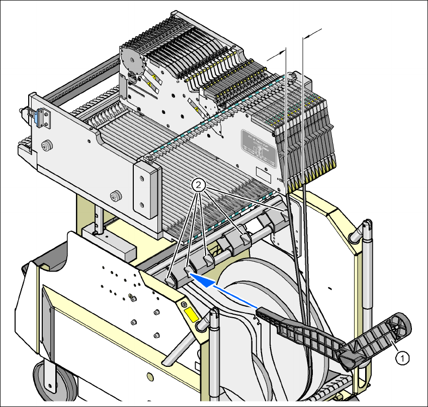
5.3.5 Support for an additional tape reel (X-series)
5
Fig. 5.3 - 3 Support for an additional tape reel (X-series)
(1) Support for an additional tape reel, item no. 00141217-xx
(2) Mounting device for the support
5
X-series feeder modules can process component tapes without problems if the lateral offset be-
tween the feeder module and the tape reel does not exceed 60 mm. If a predefined set-up means
that the maximum permitted offset cannot be maintained, we recommend that you use the mount
for an additional tape reel (item 1). Simply insert the mount into the holder (item 2) and push it until
the offset is less than the maximum permitted value of 60 mm. The component trolley has 5 hold-
ers in total. Each tape reel mount can hold 2 tape reels, which means that up to ten 15" (381 mm)
reels can be positioned above the tape container.
max. 60 mm
User manual SIPLACE X-Series 5 Tasks on the machine
Software Version SR.601.xx 11/2005 US Edition 5.3 Carrying out a walk-through inspection
255
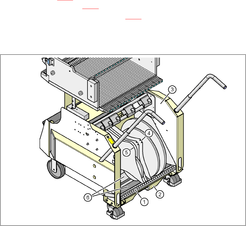
5.3.6 Inserting separating plates in the tape container
Æ The separating plate has different edges and can be inserted into the tape container in two
ways. If spindles are used, the recesses for the spindles in the separating plate point upwards
(see item 4 in Fig. 5.3 - 4
). If you do not use spindles, the
rounded
edge of the separating plate
points up (see item 5 in Fig. 5.3 - 4
).
Æ Insert the separating plates as shown in Fig. 5.3 - 4 and remember that the smallest division
of the tape container is a 2x division. This will help avoid placement errors.
Æ Check that the separating plates engage in the same positions on the three guide rails. Oth-
erwise the separating plate will be offset or bent.
5
Fig. 5.3 - 4 Separating plates in the tape container
(1) Guide rail for the separating plates
(2) Waste tape container
(3) Tape container
(4) Position of the separating plate if spindles are used
(5) Position of the separating plate if no spindles are used
(6) Sliding surfaces for the tape reels