X3_X4_Series machine.pdf - 第150页
3 Technical data User manual SIPLACE X-Series 3.10 Gantries Software Version S R.601.xx 11/2005 US Edition 150 3.10.3 Position of the gantries for th e X2 placement machine 3 Fig. 3.10 - 3 Position of the gantries for th…
User manual SIPLACE X-Series 3 Technical data
Software Version SR.601.xx 11/2005 US Edition 3.10 Gantries
149
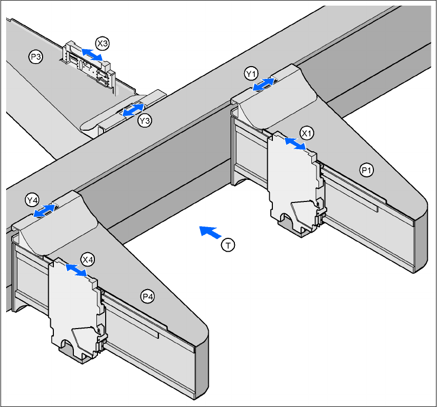
3.10.2 Position of the gantries for the X3 placement machine
3
Fig. 3.10 - 2 Position of the gantries for the X3 placement machine
G1 Gantry 1
X1 X axis, gantry 1
Y1 Y axis, gantry 1
P3 Gantry 3
X3 X axis, gantry 3
Y3 Y axis, gantry 3
P4 Gantry 4
X4 X axis, gantry 4
Y4 Y axis, gantry 4
(T) Direction of PCB transport
Placement area 2
Placement area 1
3 Technical data User manual SIPLACE X-Series
3.10 Gantries Software Version SR.601.xx 11/2005 US Edition
150
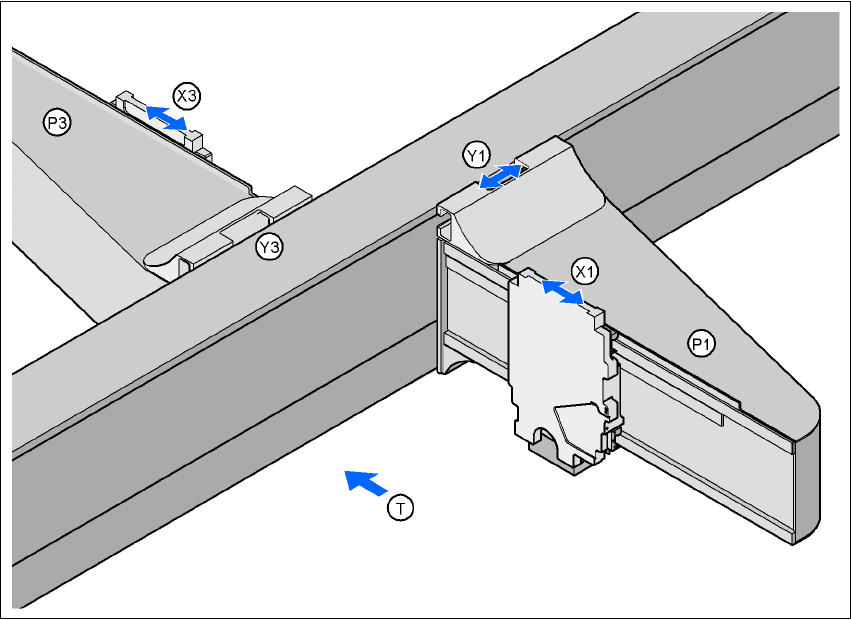
3.10.3 Position of the gantries for the X2 placement machine
3
Fig. 3.10 - 3 Position of the gantries for the X2 placement machine
G1 Gantry 1
X1 X axis, gantry 1
Y1 Y axis, gantry 1
P3 Gantry 3
X3 X axis, gantry 3
Y3 Y axis, gantry 3
(T) Direction of PCB transport
The gantry system consists of two functional groups
–X axis and
–Y axis
Placement area 2
Placement area 1
User manual SIPLACE X-Series 3 Technical data
Software Version SR.601.xx 11/2005 US Edition 3.10 Gantries
151
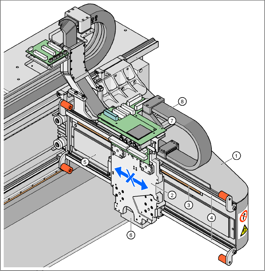
3.10.4 Structure of the X axis
3
Fig. 3.10 - 4 Structure of the X axis
(1) Gantry arm
(2) Head mount with X-axis linear motor (primary part)
(3) Linear distance measuring system
(4) Guide system
(5) Permanent magnet (secondary part of the X-axis linear motor)
(6) Sub-gantry camera
(7) Head boards
(8) Cable and hose carrier