X3_X4_Series machine.pdf - 第351页
User manual SIPLAC E X-Series 6 Component han dling Software Vers ion SR.601.xx 11/2005 US Edition 6.7 SIPLACE HF component trolleys 351 CAU TIO N 6 The com ponent tr olleys fro m the SIP LACE HF m ay only be docke d int…
6 Component handling User manual SIPLACE X-Series
6.7 SIPLACE HF component trolleys Software Version SR.601.xx 11/2005 US Edition
350
6.7 SIPLACE HF component trolleys
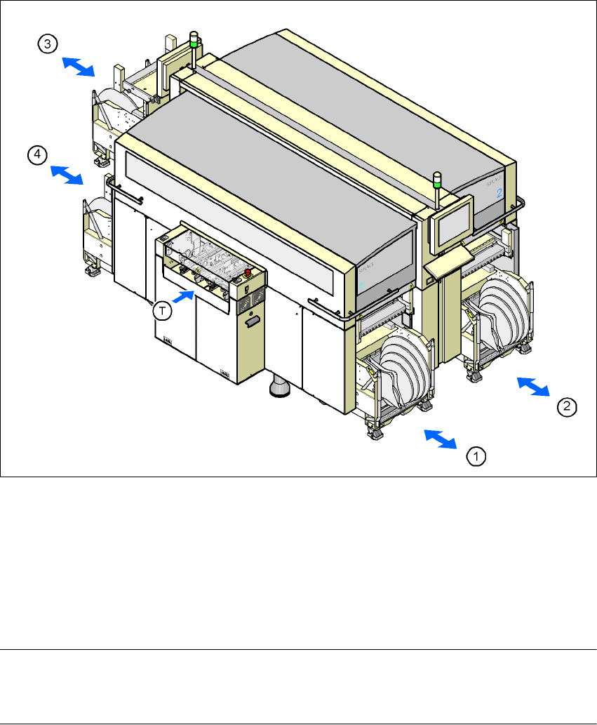
Up to four SIPLACE HF component trolleys can be docked into the machines from the SIPLACE
X-series. The locations are numbered as shown in the diagram below.
6
Fig. 6.7 - 1 Component trolley locations, SIPLACE HF
(1) Location 1
(2) Location 2
(3) Location 3
(4) Location 4
(T) PCB direction of travel
PLEASE NOTE 6
The SIPLACE HF component trolley cannot be used together with the 20-segment Collect &
Place head.
User manual SIPLACE X-Series 6 Component handling
Software Version SR.601.xx 11/2005 US Edition 6.7 SIPLACE HF component trolleys
351
CAUTION 6
The component trolleys from the SIPLACE HF may only be docked into locations at which the
component trolley docking unit for the SIPLACE HF is installed (Fig. 5.10 - 6, page 281).
The component changeover tables are stand-alone modules that can be set up with feeders at an
external set-up area. This means that the production process only has to be interrupted briefly in
order to change the component trolley.
PLEASE NOTE:
At external set-up positions, you will need an external power supply for the component trolley
(see section 6.7.5, page 357).
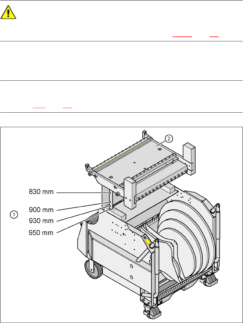
Fig. 6.7 - 2 SIPLACE HF component trolley with a PCB conveyor height of 950 mm
6
(1) Holes in the guide columns for the transport heights of 830 to 950 mm
(2) Component trolley table

6 Component handling User manual SIPLACE X-Series
6.7 SIPLACE HF component trolleys Software Version SR.601.xx 11/2005 US Edition
352
The design places considerable emphasis on ergonomics and safe operation.
– The trolleys move easily.
– No cables have to be plugged in to supply the component trolleys with power and compressed
air. The same applies to the communication interface.
– The component trolley is docked in/out the machine using a docking unit. A description of this
device can be found in chapter 5
, section 5.10, from page 275 onward. It is integrated into the
safety, supply and communication circuit or is disconnected from this circuit. Electronic prox-
imity switches signal whether the component trolley has been docked in correctly.
– The component trolley is fixed so precisely to the placement machine that it is even suitable
for processing 0201 components.
– The component trolley can be adjusted to PCB transport heights of 830 mm, 900 mm, 930 mm
and 950 mm in just a few simple actions.
– The tape container can hold tape reels with a diameter of up to 15" (optional up to 19").
– Every component trolley has a unique identification number.