X3_X4_Series machine.pdf - 第117页
User manual SIPLAC E X-Series 3 Technical data Software Vers ion SR.601.xx 11/ 2005 US Ed ition 3.7 Placem ent heads 117 3.7 Placement heads 3.7.1 Head modularity One cruci al advantage of the SIPLACE X-series is the mod…
3 Technical data User manual SIPLACE X-Series
3.6 Overview of the modules Software Version SR.601.xx 11/2005 US Edition
116
3.6 Overview of the modules
3
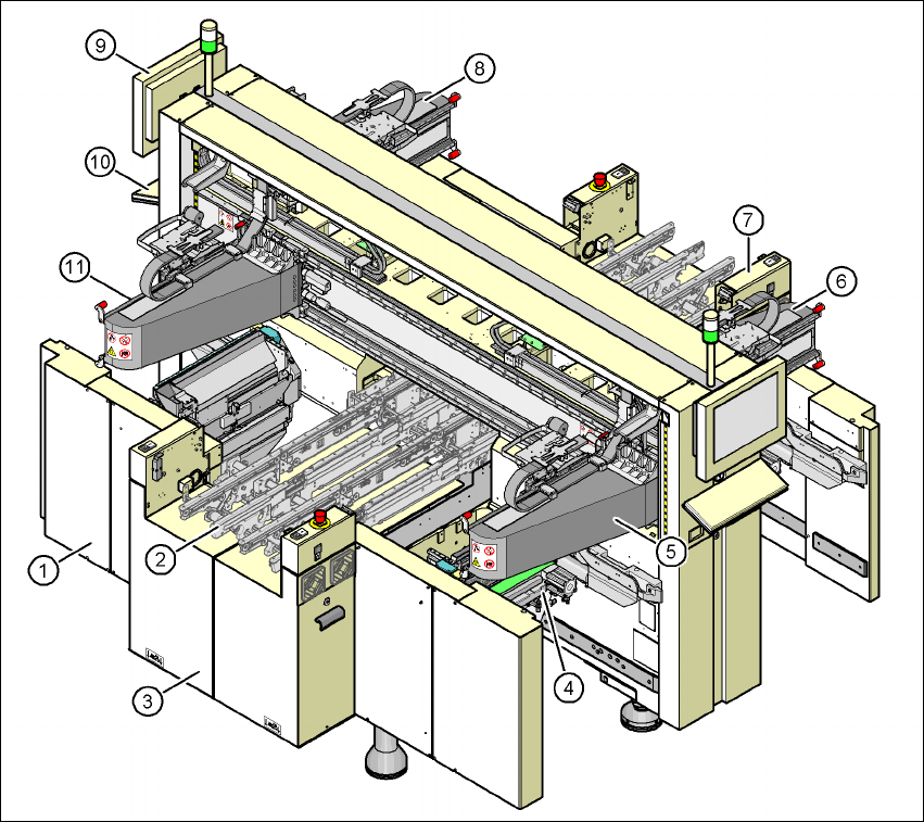
Fig. 3.6 - 1 X4 machine - protective covers and covers
(1) Machine frame
(2) PCB conveyor (flexible dual conveyor)
(3) Extension kit on the PCB input side
(4) Component trolley docking unit, tape cutter, used tape channel (4x)
(5) Gantry 1 with placement head (X4, X3 and X2)
(6) Gantry 2 with placement head (X4)
(7) Extension kit on the PCB output side
(8) Gantry 3 with placement head (X4, X3 and X2)
(9) Monitor (2x)
(10) Keyboard (2x)
(11) Gantry 4 with placement head (X4 and X3)
User manual SIPLACE X-Series 3 Technical data
Software Version SR.601.xx 11/2005 US Edition 3.7 Placement heads
117
3.7 Placement heads
3.7.1 Head modularity
One crucial advantage of the SIPLACE X-series is the modularity of the placement heads. For ex-
ample, the placement heads on the gantries can be quickly changed and adapted to the place-
ment requirements. In this section, we have put together the standard configuration for you.
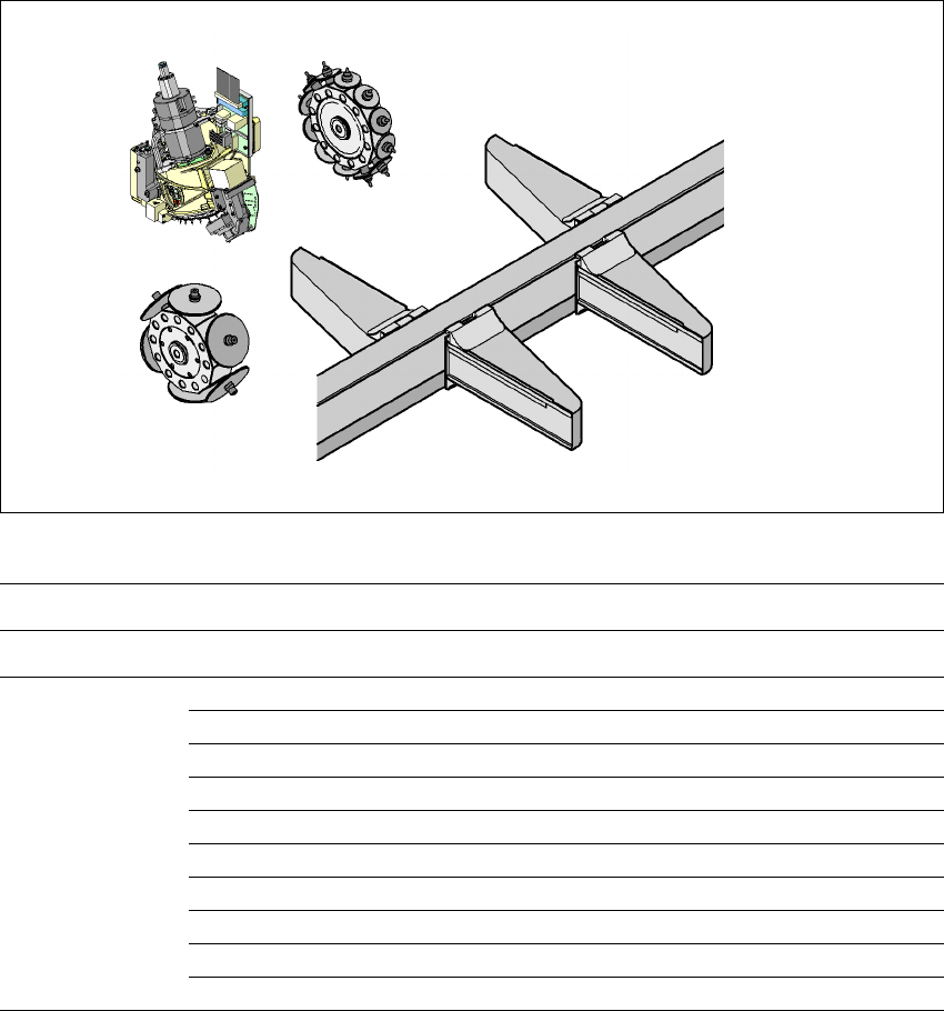
3.7.1.1 Placement head configuration on the X4 placement machine
3
Fig. 3.7 - 1 Head modularity - SIPLACE X4
C&P12
C&P6
Placement area 2
G1
G2
G3
G4
C&P20/C&P12/C&P6
C&P20/C&P12/C&P6
C&P20/C&P12/C&P6
C&P20/C&P12/C&P6
C&P20
Placement area 1
Placement area 1 Placement area 2
Gantry 1 Gantry 4 Gantry 2 Gantry 3
Placement head C&P20 C&P20 C&P20 C&P20
C&P20 C&P20 C&P12 C&P12
C&P20 C&P20 C&P12 C&P6
C&P20 C&P20 C&P6 C&P6
C&P12 C&P12 C&P12 C&P12
C&P12 C&P12 C&P12 C&P6
C&P12 C&P12 C&P6 C&P6
C&P12 C&P6 C&P12 C&P6
C&P12 C&P6 C&P6 C&P6
C&P6 C&P6 C&P6 C&P6
3 Technical data User manual SIPLACE X-Series
3.7 Placement heads Software Version SR.601.xx 11/2005 US Edition
118
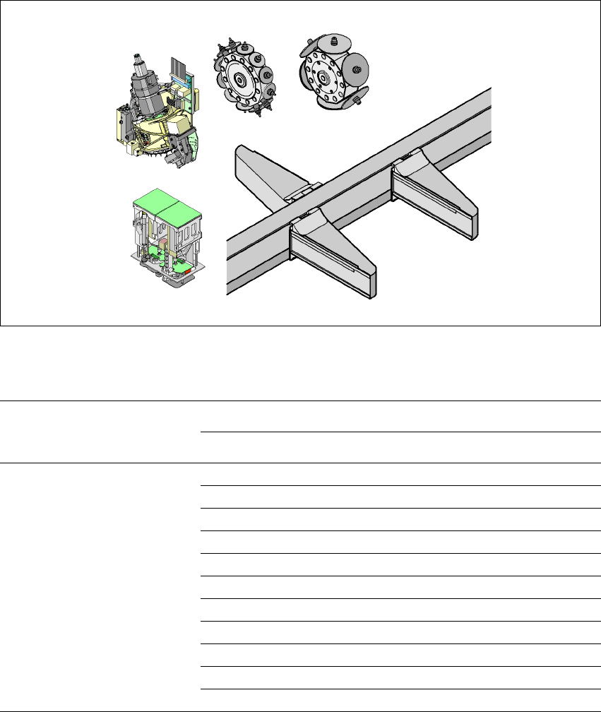
3.7.1.2 Placement head configuration on the X3 placement machine
3
3
Fig. 3.7 - 2 Head modularity - SIPLACE X3
Placement area 2
Placement area 1
TH
C&P12
G1
G3
G4
C&P20/C&P12/C&P6/TH
C&P20/C&P12/C&P6
C&P20/C&P12/C&P6
C&P6
C&P20
Placement area 1 Placement area 2
Gantry 1 Gantry 4 Gantry 3
Placement head C&P20 C&P20 C&P20
C&P20 C&P20 C&P12
C&P20 C&P20 C&P6
C&P20 C&P20 TH
C&P12 C&P12 C&P12
C&P12 C&P12 C&P6
C&P12 C&P12 TH
C&P12 C&P6 C&P6
C&P12 C&P6 TH
C&P6 C&P6 C&P6
C&P6 C&P6 TH