X3_X4_Series machine.pdf - 第238页
4 Setting up and commissioning User manual SIPLACE X-Series 4.5 Adapting the SI PLACE X- series component trolley to the PCB transport height Software V ersion SR.601.xx 11/2005 US E dition 238 4 Fig. 4.5 - 1 Com ponent …
User manual SIPLACE X-Series 4 Setting up and commissioning
Software Version SR.601.xx 11/2005 US Edition 4.5 Adapting the SIPLACE X-series component trolley to the PCB transport height
237
Æ Make sure that you do not unscrew the middle machine feet so far that the machine is no
longer adjusted.
4
4
4
4
4
4
4
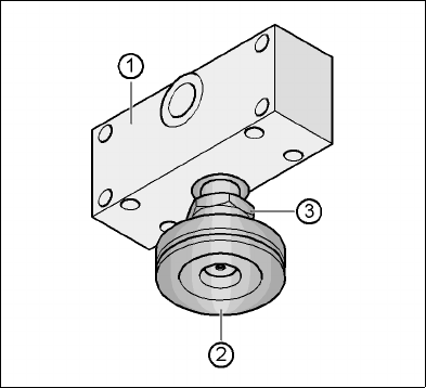
Fig. 4.4 - 28 Aligning and locking the middle machine foot
(1) Spacer
(2) Middle machine foot
(3) M24 lock nut
4
Æ Use the spirit level to ensure that the placement machine is precisely aligned.
Æ Use the size 65 open-ended spanner to tighten the M24 lock nut (item 4).
4
4
4
4
4.5 Adapting the SIPLACE X-series component trolley
to the PCB transport height
The component trolley for the X feeder modules can be set to the following PCB transport heights
with just a few simple actions:
830 mm ± 15 mm Standard height
900 mm ± 15 mm SMEMA height
930 mm ± 15 mm SMEMA height
950 mm ± 15 mm SMEMA height 4
4 Setting up and commissioning User manual SIPLACE X-Series
4.5 Adapting the SIPLACE X-series component trolley to the PCB transport height Software Version SR.601.xx 11/2005 US Edition
238
4
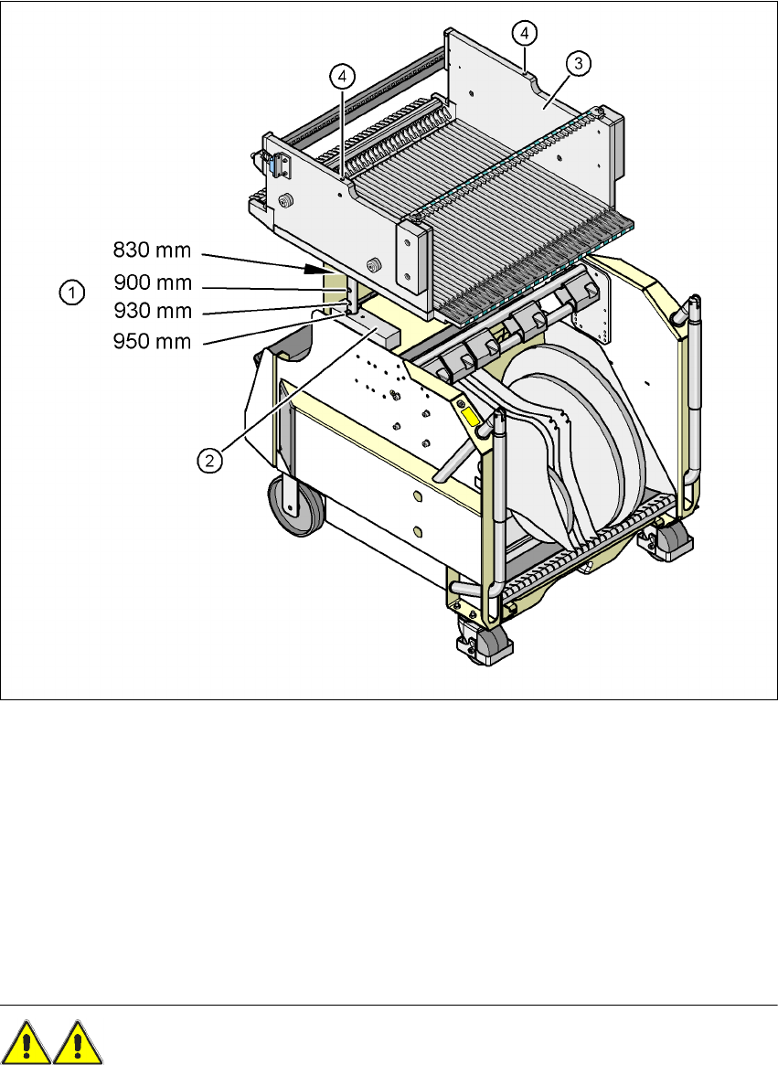
Fig. 4.5 - 1 Component trolley (SIPLACE X-series) with a PCB conveyor height of 950 mm
(1) Holes in the guide columns for the transport heights of 900, 930 and 950 mm.
If the transport height is 830 mm, the component table lies on the block (2).
(2) Block
(3) Component feeder table
(4) M8 holes for fixing the assembly guide
4.5.1 Warning instructions
WARNING 4
Only Siemens engineers or qualified personnel are permitted to adjust the component trolley
height.
User manual SIPLACE X-Series 4 Setting up and commissioning
Software Version SR.601.xx 11/2005 US Edition 4.5 Adapting the SIPLACE X-series component trolley to the PCB transport height
239
Æ Always follow the applicable accident prevention regulations.
Æ Remove all the feeder modules from the component table, if you want to adjust the height for
the component feeder table.
4.5.2 Tools and equipment
You will need the following tools and equipment to adjust the height of the component trolley:
– Hammer
– Punch, 8 mm
– Assembly guide (item no. 03015976-xx)
– Lifting device for raising the component trolley table, carrying capacity at least 80 kg
4.5.3 Changing the component trolley height
WARNING 4
Æ Remove all the feeder modules from the component table.
Æ Fit the assembly guide to the component table in order to adjust the height. This prevents the
component table becoming deformed when the table is raised or lowered.
Æ Fix the assembly guide (item 1 in Fig. 4.5 - 2) to the component table (item 4 in Fig. 4.5 - 2)
using the two hexagon socket head screws M8 x 50 (item 3 in Fig. 4.5 - 2
).
Æ Attach the hooks of the lifting device to the eye (item 2 in Fig. 4.5 - 2).
Æ Raise the component trolley bed slightly to expose the split pins (item 6 in Fig. 4.5 - 2).
Æ Use the punch to carefully tap out the split pins on both sides.
Æ Insert the spiral clamping pins into the holes for the required PCB conveyor height (see Fig.
4.5 - 1
).
Æ Lower the component trolley bed slowly until the split pins lie on the supporting blocks (item
5 in Fig. 4.5 - 2
).
Æ Dismantle the assembly guide