X3_X4_Series machine.pdf - 第79页
User manual SIPLAC E X-Series 2 Operational safety Software Vers ion SR.601.xx 11/ 2005 US Ed ition 2. 9 Energy state of the machine af ter switching off at t he main power sw itch 79 2.9 Ene rgy st ate of the mach ine a…
2 Operational safety User manual SIPLACE X-Series
2.8 Disabling the compressed air supply and discharging the pressure Software Version SR.601.xx 11/2005 US Edition
78
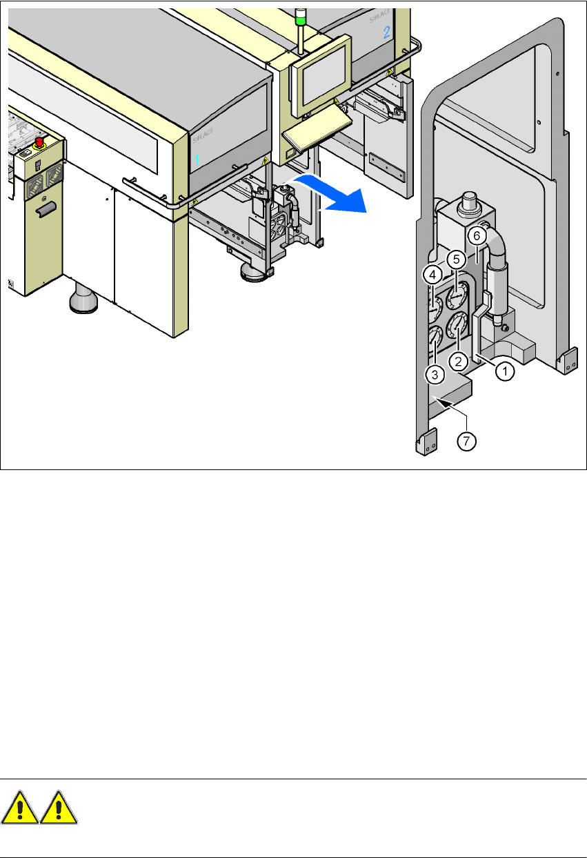
Fig. 2.8 - 1 Compressed air unit on the placement system
(1) Stop valve
(2) Manometer for the machine component supply pressure
Desired pressure: 0.48 ± 0.025 MPa, 4.8 ± 0.25 bar (display range 0 - 0.6 MPa, 0 - 6 bar)
(3) Manometer for the gantry distributor supply pressure
Desired pressure: 0.46 ± 0.01 MPa, 4.6 ± 0.1 bar (display range 0 - 0.6 MPa, 0 - 6 bar)
(4) Manometer for the bulk case feeder modules supply pressure
Desired pressure: 0.25 ± 0.05 MPa, 2.5 ± 0.5 bar (display range 0 - 0.6 MPa, 0 - 6 bar)
(5) Manometer for the input pressure
Desired pressure: 0.5 - 1.0 MPa, 5 - 10 bar (display range: 0 - 1.0 MPa, 0 - 10 bar)
(6) Compressed air filter
(7) Hexagon socket head screw for fixing the pneumatic board
WARNING
NEVER detach compressed air lines while they are still pressurized. Risk of injury. 2
User manual SIPLACE X-Series 2 Operational safety
Software Version SR.601.xx 11/2005 US Edition 2.9 Energy state of the machine after switching off at the main power switch
79
2.9 Energy state of the machine after switching off at
the main power switch
2
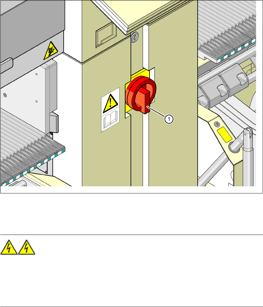
Fig. 2.9 - 1 Position of the power supply on the machine
2
WARNING
The placement system is supplied with 3 x 208 VAC, 3 x 230 VAC, 3 x 380 VAC, 3 x 400 VAC or
3 x 415 VAC ± 5 %, 50/60 Hz mains voltage. This means that some parts of the system carry po-
tentially lethal voltages - even when switched off at the main power switch. Incorrect handling of
the placement system can therefore result in death or severe injury or considerable damage to
equipment. 2
Æ Always follow the applicable accident prevention and DIN regulations (particularly DIN EN 60
204, part 1).
Æ The guard over the power supply unit must ONLY be opened by appropriately qualified and
trained personnel.
(1) Main power switch
2 Operational safety User manual SIPLACE X-Series
2.9 Energy state of the machine after switching off at the main power switch Software Version SR.601.xx 11/2005 US Edition
80
2
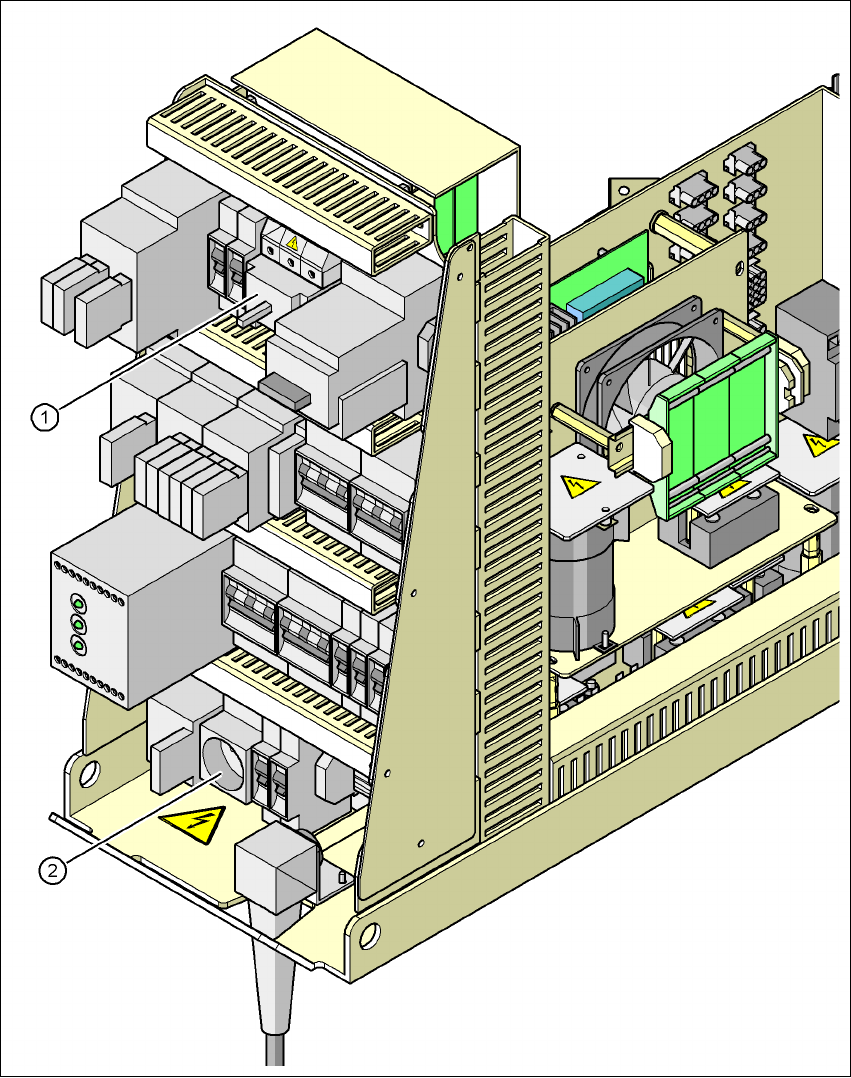
Fig. 2.9 - 2 Position of main power switch and service socket
(1) Main power switch
(2) Service socket