X3_X4_Series machine.pdf - 第154页
3 Technical data User manual SIPLACE X-Series 3.10 Gantries Software Version S R.601.xx 11/2005 US Edition 154 The Y axis essent ially cons ists of the foll owing mai n modu les: – Y -ax is linear mo tor (prim ary part) …
User manual SIPLACE X-Series 3 Technical data
Software Version SR.601.xx 11/2005 US Edition 3.10 Gantries
153
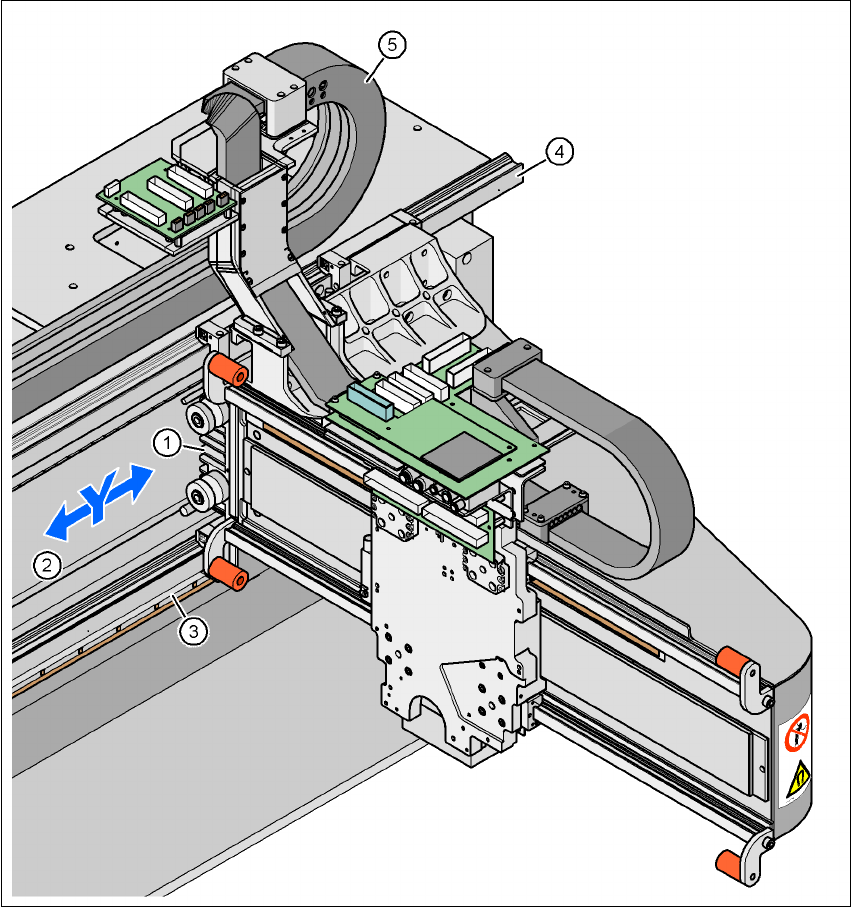
3.10.6 Structure of the Y axis
3
Fig. 3.10 - 5 Structure of the Y axis
(1) Y-axis linear motor (primary part)
(2) Permanent magnet (secondary part of the Y-axis linear motor)
(3) Linear distance measuring system
(4) Guide system
(5) Cable and hose carrier

3 Technical data User manual SIPLACE X-Series
3.10 Gantries Software Version SR.601.xx 11/2005 US Edition
154
The
Y axis
essentially consists of the following main modules:
– Y-axis linear motor (primary part) (1)
– Permanent magnet (secondary part of the Y-axis linear motor) (2)
– Linear distance measuring system (3)
– Guide system (4)
– Cable and hose carrier (5)
The Y axis is driven by a linear motor. The secondary part of the drive is made up of permanent
magnets and is mounted on the machine frame. The primary part is bolted to the gantry.
3.10.7 Technical data for the Y axis
Drive Direct, linear motor
Maximum speed 2.5 m/sec.
Traversing path 1430 mm
Distance measuring system Metal linear scale
Scale length 1850 mm
Resolution 1 µm
User manual SIPLACE X-Series 3 Technical data
Software Version SR.601.xx 11/2005 US Edition 3.11 Vision cameras
155
3.11 Vision cameras
A component camera is integrated into each Collect&Place head (see Fig. 3.7 - 5 on page 121,
Fig. 3.7 - 8
on page 129 and Fig. 3.7 - 11 on page 134). The stationary P&P component vision
camera (type 33) 55 x 45 digital for the TwinHead is permanently fixed to the machine frame.
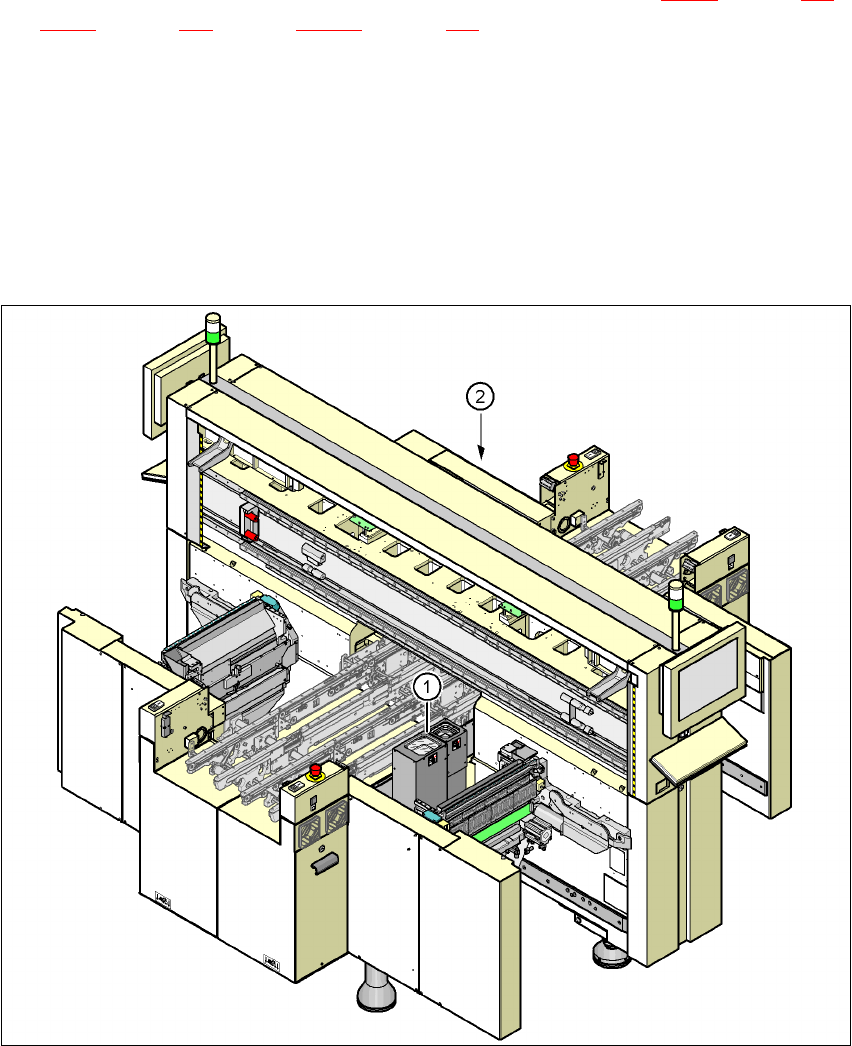
Assembly positions for the stationary P&P component camera (type 33) 55 x 45, digital 3
3
3
Fig. 3.11 - 1 Assembly positions for the stationary P&P component camera (type 33) 55 x 45, digital
(1) Assembly position for location 1 (X2 placement machine)
(2) Assembly position for location 3 (X2 and X3 placement machine)
TwinHead Stationary P&P component camera, (type 33) 55 x 45, digital
(IC camera)
Placement area 1 Location 1 (X2 placement machine)
Placement area 2 Location 3 (X2 and X3 placement machine)