X3_X4_Series machine.pdf - 第437页
User manual SIPLAC E X-Series 7 Station extensions Software Version SR.601.xx 11/2005 US Edition 7.12 Coplanarity laser module 437 7 Fig. 7.12 - 3 Warning label W216 b eside the main switch 7.12.5 LED displays on t h e c…
7 Station extensions User manual SIPLACE X-Series
7.12 Coplanarity laser module Software Version SR.601.xx 11/2005 US Edition
436
WARNING 7
Only authorized personnel may open the housing of the optical sensor.
For repair and servicing, always return the sensors to SIEMENS A&D.
PLEASE NOTE 7
When the coplanarity laser module is fitted, the placement machine must be classified as laser
class 2. The laser module is not integrated into the emergency stop circuit.
Æ Identify the machine with warning sign W208 "Laser class 2", item no. 03009347-xx (see item
W208 in Fig. 2.2 - 11
, page 45).
Æ Stick warning label W208 beside the main power switch on the cover (see item 1 in Fig. 2.9
- 1, page 79.
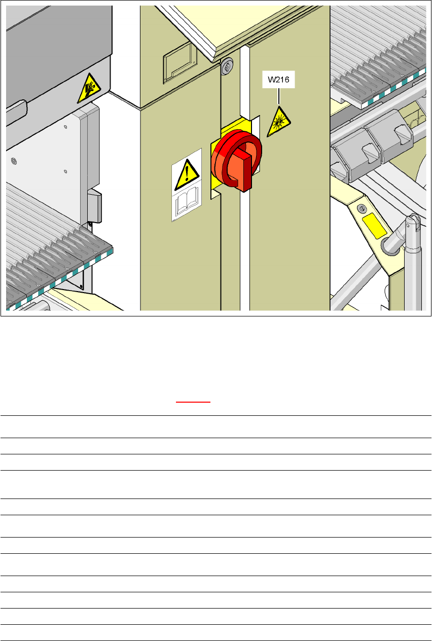
7.12.4 Warning label W216 on the cover beside the main switch
7
Warning label W216 "Laser class 2" on the cover beside the main switch,
item no. 03010316-01 (number per placement machine: 1)
PLEASE NOTE 7
When the coplanarity laser module is fitted, the placement machine must be classified as laser
class 2. The laser module is not integrated into the emergency stop circuit.
Æ Identify the machine with warning sign W216 "Laser class 2", item no. 03010316-xx.
Æ Stick warning label W216 beside the main power switch on the cover (see item W216 in Fig.
7.12 - 3
).
7
7
7
7
7
7
LASER RADIATION!
Do not look into beam
Laser class 2
User manual SIPLACE X-Series 7 Station extensions
Software Version SR.601.xx 11/2005 US Edition 7.12 Coplanarity laser module
437
7
Fig. 7.12 - 3 Warning label W216 beside the main switch
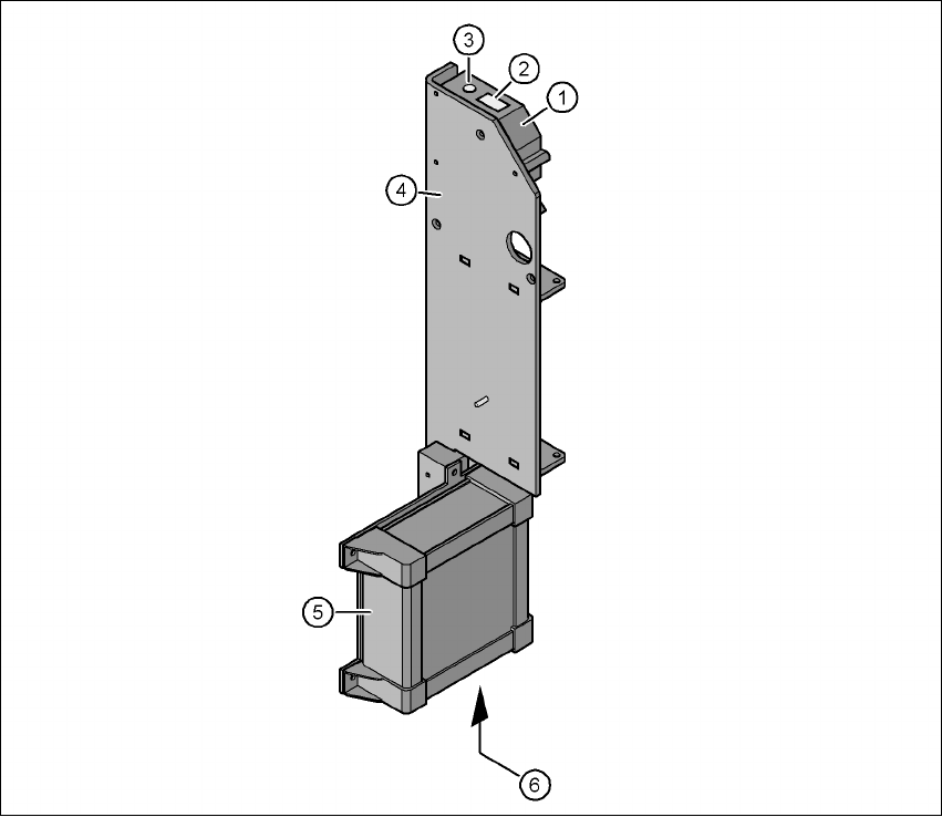
7.12.5 LED displays on the controller
The statuses of the coplanarity module are indicated by LEDs. The LEDs can be found at the bot-
tom of the controller (see item 6 in Fig. 7.12 - 4
).
LED state Status display
Green Test object in measuring range
Yellow Middle of measuring range
Red
Outside the measuring range,
with low reflection
LED Off Laser switched off
LED Power Status display
LED lights up Supply voltage present
LED avg avg1 avg2
Off Off No averaging
Red Off Averaging 1
Off Red Averaging 2
Red Red Averaging 3
7 Station extensions User manual SIPLACE X-Series
7.12 Coplanarity laser module Software Version SR.601.xx 11/2005 US Edition
438
7
Fig. 7.12 - 4 Coplanarity laser module
(1) Laser sensor
(2) Detector
(3) Laser emitter
(4) Assembly bracket
(5) Controller
(6) LED displays and connections on the controller