X3_X4_Series machine.pdf - 第236页
4 Setting up and commissioning User manual SIPLACE X-Series 4.4 Setting up the placement machine Software Version SR.601.xx 11/2005 US E dition 236 4 Fig. 4.4 - 27 Se tting the height for the outer machine feet 4 (1) Adj…
User manual SIPLACE X-Series 4 Setting up and commissioning
Software Version SR.601.xx 11/2005 US Edition 4.4 Setting up the placement machine
235
4.4.16 Making final adjustments to the placement machine
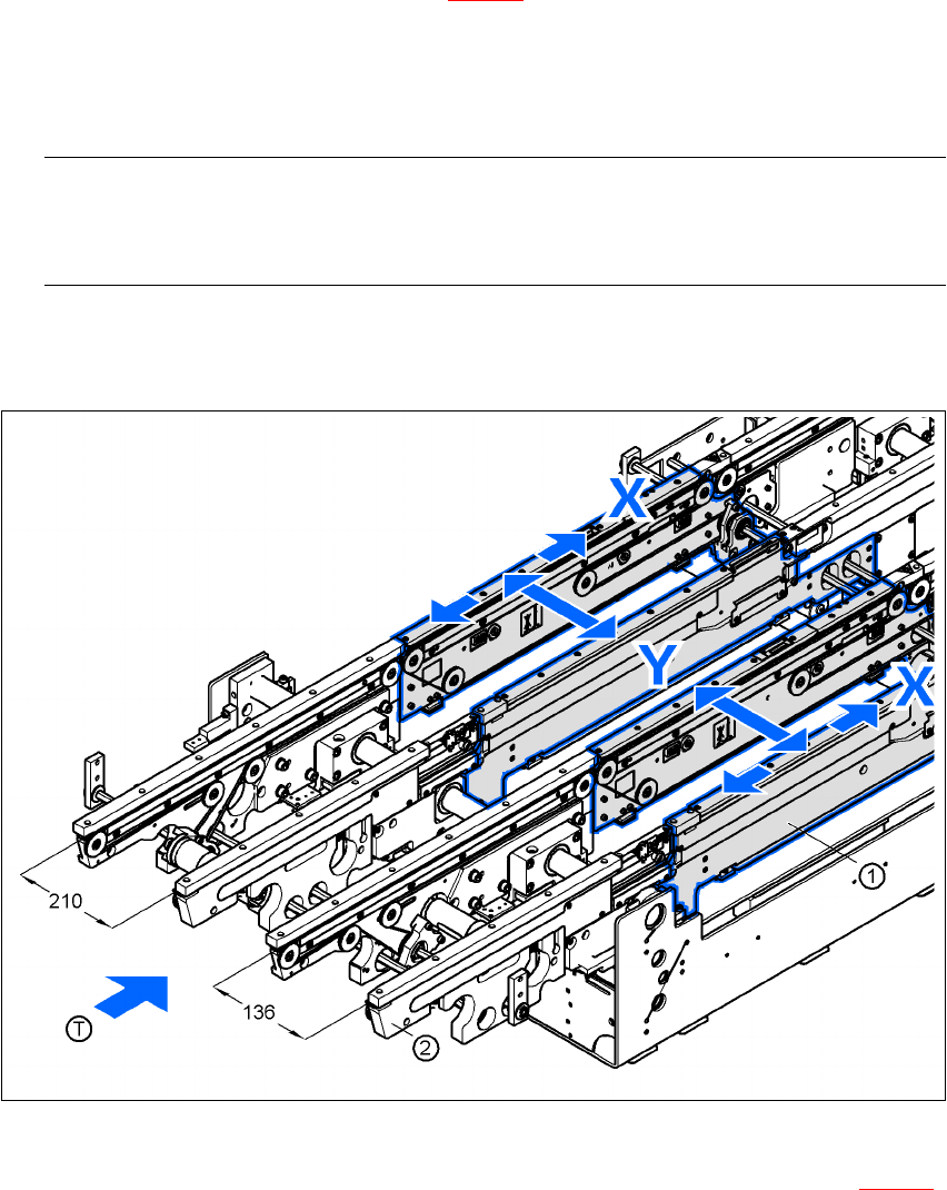
Æ Place the machine's spirit level on the panels of the PCB conveyor in placement area 1 in
both the X and the Y directions (see Fig. 4.4 - 26
). The PCB conveyor width is preset:
Single conveyor 210 mm
Dual conveyor, track 1 136 mm
Dual conveyor, track 2 210 mm 4
PLEASE NOTE: 4
On the dual conveyor, place the spirit level only on the outer panels of the machine for ad-
justing in the X direction.
Æ Measure the distance between the top edge of the PCB conveyor belt and the floor. This dis-
tance should be 800 mm, 900 mm, 930 mm or 950 mm.
4
Fig. 4.4 - 26 Adjusting the placement machine in the X and Y directions
Æ Use the size 36 fork wrench to adjust the adjusting screw M24x2x120 (item 1 in Fig. 4.4 - 27)
so that the label on the machine spirit level does not deviate from the zero point for the re-
quired PCB transport height.
4 Setting up and commissioning User manual SIPLACE X-Series
4.4 Setting up the placement machine Software Version SR.601.xx 11/2005 US Edition
236
4
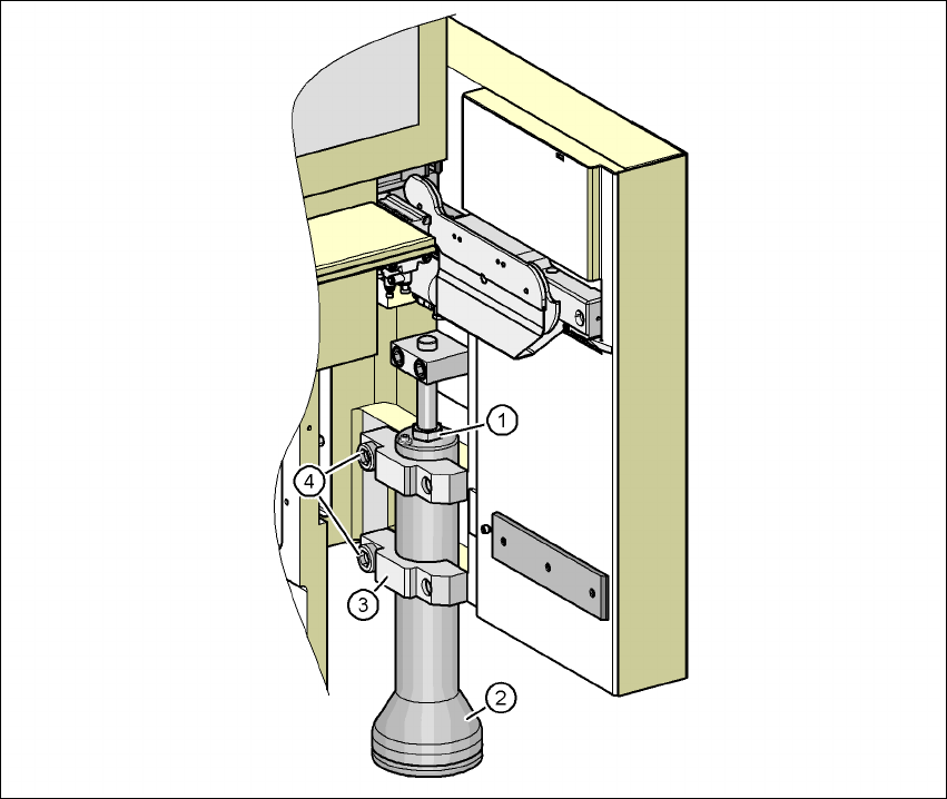
Fig. 4.4 - 27 Setting the height for the outer machine feet
4
(1) Adjusting screw M24x2x120 for adjusting the height
(2) Outer machine foot
(3) Clamp
(4) M24x90 hexagon socket head screw
Æ Check the required PCB transport height.
Æ If the placement machine has been aligned, use the size 19 Allen key to tighten the hexagon
socket head screws M24x90 (Pos. 4) for holding the clamps on all the outer machine feet
(item 3).
Æ Unscrew the middle machine feet using a hook wrench 135 - 145 until they are seated firmly
on the ground.
User manual SIPLACE X-Series 4 Setting up and commissioning
Software Version SR.601.xx 11/2005 US Edition 4.5 Adapting the SIPLACE X-series component trolley to the PCB transport height
237
Æ Make sure that you do not unscrew the middle machine feet so far that the machine is no
longer adjusted.
4
4
4
4
4
4
4
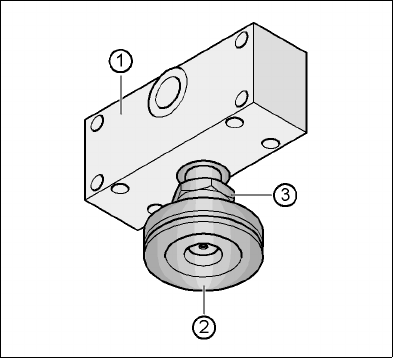
Fig. 4.4 - 28 Aligning and locking the middle machine foot
(1) Spacer
(2) Middle machine foot
(3) M24 lock nut
4
Æ Use the spirit level to ensure that the placement machine is precisely aligned.
Æ Use the size 65 open-ended spanner to tighten the M24 lock nut (item 4).
4
4
4
4
4.5 Adapting the SIPLACE X-series component trolley
to the PCB transport height
The component trolley for the X feeder modules can be set to the following PCB transport heights
with just a few simple actions:
830 mm ± 15 mm Standard height
900 mm ± 15 mm SMEMA height
930 mm ± 15 mm SMEMA height
950 mm ± 15 mm SMEMA height 4