1OM-1050-002.pdf - 第106页
Fig. 1C3-1 Fig. 1C3-2 CAUTION Do not change the set air pressure. Otherwise, the pneumatic devices will not work normally . (a) The pressure switch is correctly set. Be sure not to adjust it. Ref.: 0.40 MPa for P1 and 0.…
1.1 Inspections before Automatic Operation
1.1.1 Confirmation of Power Supply and Air Pressure
(1) Confirmation of Power Supply
Confirm that the local main breaker (the power supply to the ma-
chine) is "ON".
• Power Supply : 200±20 V AC 3-Phase
• Apparent Power : TCM-X100: Approx. 16 kVA
TCM-X200: Approx. 16 kVA
TCM-X300: Approx. 16 kVA
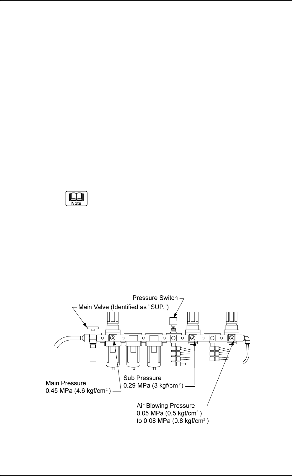
(2) Confirmation of Air Pressure
Confirm that the air pressure is set to the value specified below.
• Main Pressure : 0.45 MPa (4.6 kgf/cm
2
)
The above represents the pressure specified while the
machine is in the "STOP" mode.
Min. 0.4 MPa (4.1 kgf/cm
2
) is required while the machine
is running.
• Sub Pressure : 0.29 MPa (3 kgf/cm
2
)
• Air Blowing Pressure: 0.05 MPa (0.5 kgf/cm
2
) to
0.08 MPa (0.8 kgf/cm
2
)
• Pressure of Z Clamp: 0.2 MPa (2.0 kgf/cm
2
)
Fig. 1C3
1.1 Inspections before Automatic Operation
0307-006 3-2 AFO01EOPP
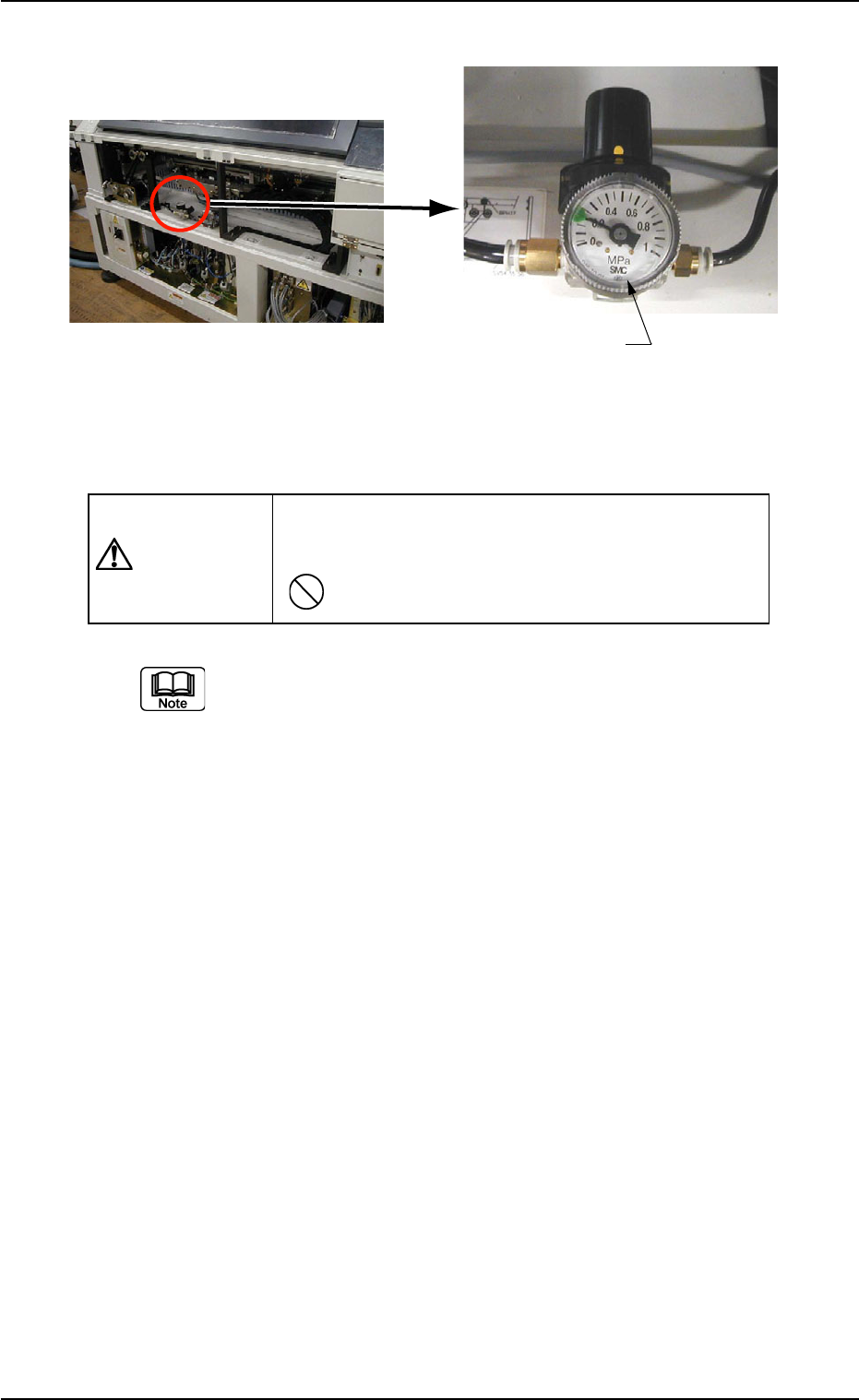
Fig. 1C3-1 Fig. 1C3-2
CAUTION
Do not change the set air pressure. Otherwise, the
pneumatic devices will not work normally.
(a) The pressure switch is correctly set. Be sure not to adjust
it.
Ref.: 0.40 MPa for P1 and 0.35 MPa for P2
(b) Never adjust the air blowing pressure. The pressure is al-
ready set to "0.05 MPa (0.5 kgf/cm
2
) to 0.08 MPa (0.8 kgf/
cm
2
)".
(c) Use of Dry and Clean Air
Be sure to use dry and clean air. If moisture, oil, dust, etc.,
enter a pneumatic device (air cylinder, etc., used in this
machine), it will result in a breakdown of the machine.
Dry and Clean Air
Moisture : Dew Point -17°C or lower (Atmospheric Pres-
sure)
Oil : 0.1 mg/m
3
or less (ANR)
Dust : Solid Material 0.01 µm or less
1.1 Inspections before Automatic Operation
0301-004 3 - 3 AFO01EOPP
2TGUUWTGQH<%NCOR
0.2 MPa (2.0 kgf/cm )
2
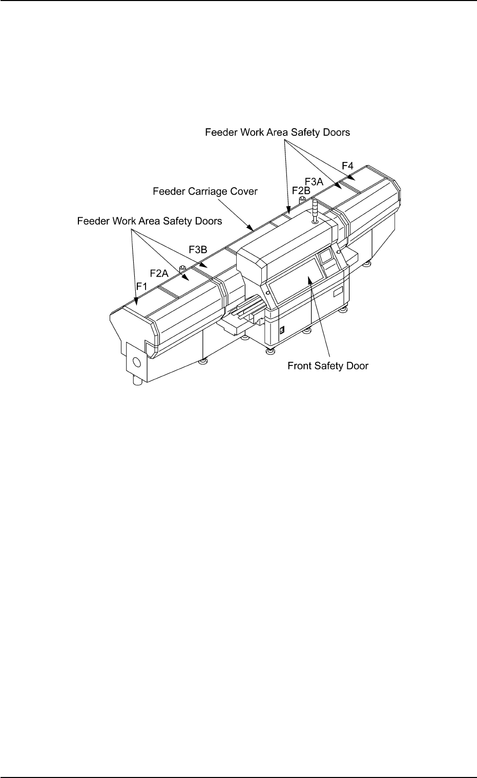
1.1.2 Confirmation of Front Safety Door and Feeder Carriage
Sections
Confirm that the front safety door, the feeder work area safety doors,
and the feeder carriage covers are completely closed.
Fig. 1C4
0102-002 3 - 4
AFO01EOPP
1.1 Inspections before Automatic Operation